
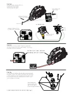

Battery Replacement:
Remove these 4 screws,
gently lift the pickguard’
remove and replace the battery.
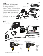
RING
TIP
SLEEVE
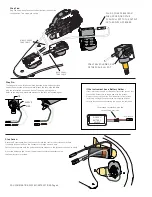
Step Nine:
Plug the Battery clip cable onto the BAT- (BLACK) and the BAT+ (RED)
terminals of the PC Board. The extra terminal marked V+ is for powering
additional EMG Accessories (see page 6).
Step Ten:
This completes the installation. Plug the battery clip onto the battery.
We suggest you plug in the instrument, tap lightly on the pickups with
a small screwdriver to make sure the pickups are working correctly.
When the battery needs to be replaced (about 6 months to 1 year)
refer to the diagram at the right.
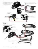
Step Eight:
Plug the Output cable from the Output Jack to
H2 of the Push-Pull Pot as shown.
Plug the green wire onto the Ring
terminal of the Switch PC Board.
TONE
INPUT
MID
P/U
NEK
P/U
BLK
WHT
OUTPUT
SLV
TIP
RING
V+
GRN
RED
RED
BLK
WHT
BLK
WHT
BLK
BRG
BLK
WHT
RED
EMG-S5
NEK
MID
B161rC
BATTERY CLIP TO BAT- AND BAT+
TERMINALS ON THE PC BOARD
GREEN WIRE FROM OUTPUT JACK
TO THE RING PIN OF THE PC BOARD
TONE
INPUT
MID
P/U
NEK
P/U
BLK
WHT
OUTPUT
SLV
TIP
BAT-
BAT+
V+
GRN
RED
RED
BLK
WHT
BLK
WHT
BLK
BRG
BLK
WHT
RED
EMG-S5
NEK
MID
B161rC
H2 OF PUSH-PULL POT
TO OUTPUT JACK
S/S/89 COMBINATION SYSTEM INSTRUCTIONS Page 5
ALTERNATE VIEW
- 9V +
GREEN WIRE TO THE RING
TERMINAL OF THE PC BOARD
TO OUTPUT JACK
1
2
3
H2 OF PUSH-PULL POT
TO OUTPUT JACK


