

S/S/89 COMBINATION SYSTEM INSTRUCTIONS Page 2
General Notes:
Every attempt has been made to make this a solderless installation.
There are some instances where this is not possible;
1) If your instrument uses the long panel output jack and you had
passive pickups you will need a new stereo output jack, the
Switchcraft 152B is recommended. Soldering to the new jack will be
required, see the Power Tips Data sheet at http://www.emgpickups.com
2) Some instruments may already have a battery holder installed and in that
case soldering may be required, see page 4.
Installing EMG Combination Systems is very easy and is accomplished in a
few steps. The controls included have a 10 mm bushing height so they can
be used either on a pickguard, or body mount. The cable lengths are
designed for a pickguard, so you should make sure they are long enough if
you are mounting the system into a body. Longer cable lengths may be
required. If a cable is too long, any extra cable length should be kept
under the pickup
Installation Instructions:
EMG-S/S/89 Combination Systems
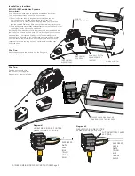
Step One:
Mount the pickups and the controls onto the Pickguard,
or into the guitar body.
1
2
3
TONE CONTROL
MIDDLE PICKUP
TONE CONTROL
NECK PICKUP
PUSH-PULL SWITCH
VOLUME CONTROL
(MASTER)
EMG-S5
5 POSITION SWITCH
EMG-89 or 81-TW
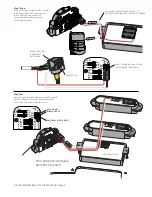
Step Two:
Plug the pickup cable onto
the Push-Pull Pot using either
Diagram #1 or Diagram #2 below.
Diagram #1
HUMBUCKING ON: DOWN POSITION
SINGLE COIL ON: UP POSITION
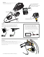
Diagram #2
SINGLE-COIL ON: DOWN POSITION
HUMBUCKING ON: UP POSITION
FLIP CONNECTORS 1 AND 2
AS SHOWN
WIRE ORDER:
WHITE
GREEN
BLUE
YELLOW
ORANGE
SHIELD
WIRE ORDER:
GREEN
WHITE
YELLOW
BLUE
ORANGE
SHIELD
1
2
3
1
2
3
CHOOSE EITHER DIAGRAM #1 OR
DIAGRAM #2 FOR THE WIRE ORDER


