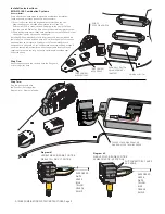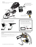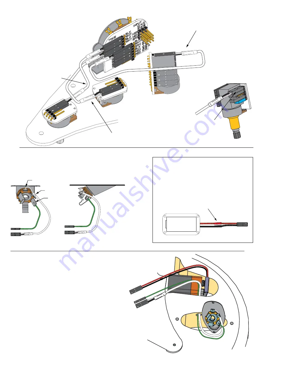
If the instrument has a Battery Holder:
If your instrument has a 9 or 18-Volt battery holder you can still
use the EMG Connectors to supply power to the pickups.
Simply cut and strip the wires from the battery clip provided.
Twist the wires together and use the shrink tubing included
to cover the connections. Soldering the wires is the preferred.
Cover these connections with the
shrink tubing provided.
To PC Board
9/18 VOLT
BATTERY
HOLDER
TO EMG-S5 SWITCH
RING
TIP
SLEEVE
SSH COMBINATION SYSTEM INSTRUCTIONS Page 4
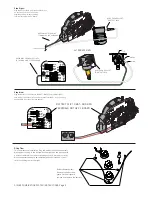
Step Six:
The Pickguard is now fully assembled. Next the pre-wired output jack
needs to be mounted in the Jack plate. Mount the Jack onto the plate
with the orientation as shown with the Tip spring pointing down.
Refer to the diagrams below and make sure the Jack is mounted tightly.
Step Seven:
Route the Output cable from the Jack cavity into the control cavity via the small hole.
If the hole is too small, Push the connectors through one at a time
Fasten the Jack plate onto the guitar and test to make sure the jack inserts and exits easily.
Mount the battery in the control compartment. Insulate the battery using
the foam insulator provided..
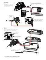
Step Five:
Plug the Volume and Tone control cables from the controls
to the switch. Two views are shown.
MIDDLE PICKUP
TONE CABLE
NECK PICKUP
TONE CABLE
PLUG A COAX CABLE FROM
THE H1 POSITION OF THE
PUSH-PULL POT TO THE OUTPUT
OF THE SWITCH PC BOARD
1
2
3
COAX CABLE SHOWN ON H1
OF THE PUSH-PULL POT


