Hardware Reference Manual
Hardware Interface
GFK-3022E
September 2021
Hardware Interface
32
5.1
Interface
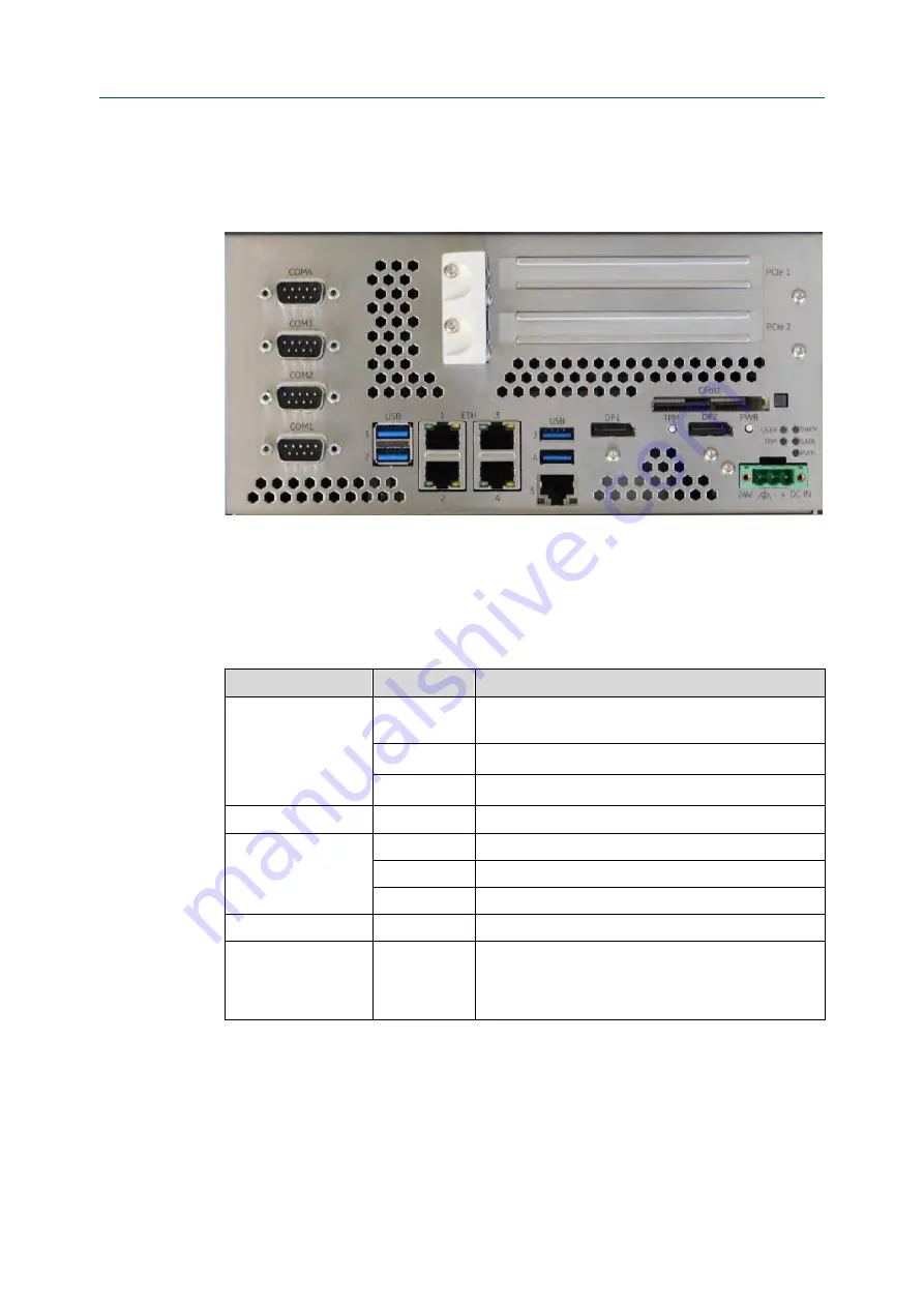
Figure 5-2
RXi2-XP IPC Hardware Interface Overview (2-slot Option)
5.1.1
Status LEDs
The RXi2-XP IPC contains a set of status LEDs to indicate various functions. The CEC09 provides
LEDs on the front panel, in a location near the power connector and power button.
Table 5-1
Status LEDs
LED Name
Color
LED Status Indication
PWR (Power)
Red
Standby power available, but no power good signal active
(error condition)
Yellow
Standby power valid (S3, S4, S5)
Green
All power available and valid (S0)
SATA
Green
SATA access in progress (SATA, CFAST, M.2)
THRM
(Port Expander:
P0: Green; P1: Red)
Green
Thermal OK
Yellow
T
Hot
reached (available also in S5 after Shutdown)
Red
T
Crit
reached (available also in S5 after Shutdown)
USER (GPO0)
Green
Switchable from User
TPM
(Port Expander:
P2: Green and Red)
Yellow
Flashes when TPM button is pressed for a defined amount
of time

