Quick Installation Guide
00825-0500-4809, Rev CA
September 2003
Threaded Flo-Tap 485 Annubar
S
TEP
3: I
NSTALL
I
SOLATION
V
ALVE
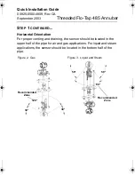
1. Thread the guide nipple into the mounting.
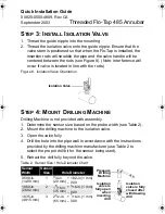
2. Thread the isolation valve onto the guide nipple. Ensure that the
valve stem is positioned so that when the Flo-Tap is installed, the
insertion rods will straddle the pipe and the valve handle will be
centered between the rods (see Figure 8). (Note: Interference will
occur if valve is located in line with the rods.)
Figure 8. Isolation Valve Orientation
S
TEP
4: M
OUNT
D
RILLING
M
ACHINE
Drilling Machine is not provided with assembly.
1. Determine the sensor size based on the probe width (see Table 2).
2. Mount the drilling machine to the isolation valve.
3. Open the valve fully.
4. Drill the hole into the pipe wall in accordance with the instructions
provided by the drilling machine manufacturer (use Table 2 to
select the proper drill bit for the sensor being used).
5. Retract the drill fully beyond the valve.
Table 2. Sensor Size / Hole Diameter Chart
Sensor
Width
Sensor
Size
Hole Diameter
0.590-in.
(14.99 mm)
1
3
/
4
-in.
(20 mm)
+ 1/32-in (1 mm)
– 0.00
1.060-in.
(26.92 mm)
2
1
5
/
16
-in.
(35 mm)
+
1
/
16
-in. (1 mm)
– 0.00
1.935-in.
(49.15 mm)
3
2
1
/
2
-in.
(65 mm)
+
1
/
16
-in. (1 mm)
– 0.00
Isolation Valve
Pressure
Drilling
Machine
Isolation
valve is fully
closed after
withdrawing
drill
Isolation
valve is
fully open
when
inserting
drill
4809-0500 Rev CA.fm Page 10 Monday, September 22, 2003 11:14 AM

