


Installation and Use Manual
15
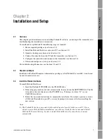
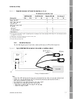
Installation and Setup
Pr
oL
in
k II
Setup
T
ransmitter Star
tup
Usi
ng
Pr
oL
in
k
II
Be
fo
re
Y
o
u
Begin
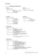
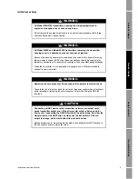
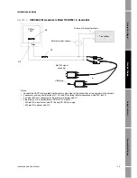
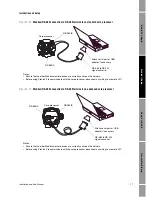
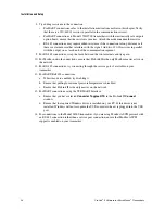
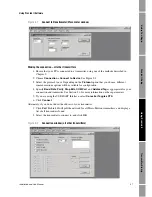
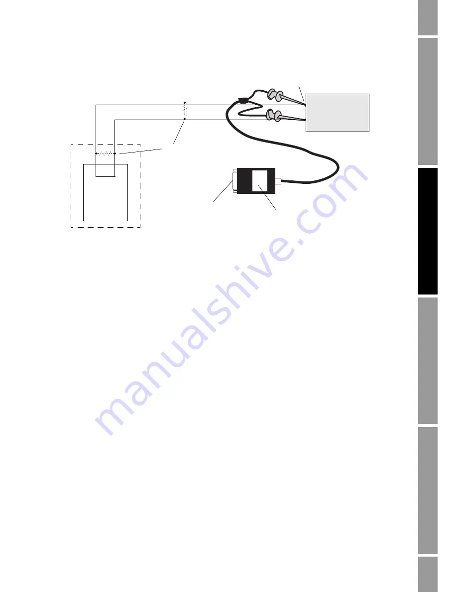
Figure 2-7
Modbus/RS-485 connection to transmitter or multidrop network
DCS or
PLC
R1
Attach serial port or USB
adapter if necessary (not
shown)
RS-485 terminals
Transmitter
RS-232 <-> 2-wire RS-485
interface converter
Notes:
• Connect the interface leads to the RS-485 terminals on the transmitter, or to any point on the network.
• Ensure that no other Modbus master devices are currently active on the network.
• For RFT9712 transmitters, set the jumper for RS-485 communications.
• For long-distance communication, or if noise from an external source interferes with the signal, add two 120-
Ω
terminating resistors (R1) at each end of the RS-485 network.
Содержание Network Router
Страница 6: ...iv ProLink II Software for Micro Motion Transmitters ...
Страница 12: ...6 ProLink II Software for Micro Motion Transmitters ...
Страница 42: ...36 ProLink II Software for Micro Motion Transmitters ...
Страница 64: ...58 ProLink II Software for Micro Motion Transmitters ...
Страница 66: ...60 ProLink II Software for Micro Motion Transmitters ...
Страница 70: ...64 ProLink II Software for Micro Motion Transmitters ...
Страница 78: ...72 ProLink II Software for Micro Motion Transmitters ...
Страница 94: ...88 ProLink II Software for Micro Motion Transmitters ...
Страница 95: ......


