background image

13

Functional Safety Manual

M310/FSM, Rev BA

Operation and Maintenance

April 2017

Operation and Maintenance

Section  5

Operation and Maintenance

5.1

Proof-test requirement

During operation, a low-demand mode SIF must be proof-tested. The objective of proof-testing is to 
detect failures within the equipment in the SIF that are not detected by any automatic diagnostics of the 
system. Undetected failures that prevent the SIF from performing its function are the main concern.

Periodic proof-tests shall take place at the frequency (or interval) defined by the SIL verification 
calculation. The proof-tests must be performed more frequently than or as frequently as specified in the 
SIL verification calculation in order to maintain the required safety integrity of the overall SIF.

A sample procedure is provided in 

Appendix A: Proposed Proof-test Procedure

Results from periodic proof tests shall be recorded and periodically reviewed.

5.2

Repair and replacement

Repair procedures in the product manual 

M310

 must be followed.

5.3

Notification of failures

In case of malfunction of the system or SIF, the Mobrey Magnetic Level Switch (“level switch”) shall be put 
out of operation and the process shall be kept in a safe state by other measures.

Emerson must be informed when the level switch is required to be replaced due to failure. The occurred 
failure shall be documented and reported to Emerson using the contact details on the back page of this 
functional safety manual. This is an important part of Emerson’s SIS management process.

5.4

Useful lifetime

According to the Section 7.4.9.5 of IEC 61508-2, a useful lifetime based on experience should be 
assumed.

Although a constant failure rate is assumed by the probabilistic estimation method (see FMEDA report), 
this only applies provided that the useful lifetime

(1)

 of components is not exceeded. Beyond their useful 

lifetime, the result of the probabilistic calculation method is therefore meaningless as the probability of 
failure significantly increases with time. The useful lifetime is highly dependent on the subsystem itself 
and its operating conditions.

This assumption of a constant failure rate is based on the bath-tub curve. Therefore, it is obvious that the 
PFD

AVG

 calculation is only valid for components that have this constant domain and that the validity of 

the calculation is limited to the useful lifetime of each component.

Based on general field failure data and manufacturer component data, a useful life period of 
approximately 10 to 15 years is expected for the Mobrey level switch. When plant experience indicates a 
shorter useful lifetime than indicated here, the number based on plant experience should be used.

1. 

Useful lifetime is a reliability engineering term that describes the operational time interval where the failure rate of a device is relatively constant. It is not a term which covers 
product obsolescence, warranty, or other commercial issues.

Содержание Mobrey Series

Страница 1: ...Functional Safety Manual M310 FSM Rev BA April 2017 Mobrey Magnetic Level Switches Functional Safety Manual ...

Страница 2: ......

Страница 3: ...tion 6 4Section 3 Designing a Safety Function Using the Level Switch 3 1 Safety function 7 3 2 Environmental limits 7 3 3 Application limits 7 3 4 Design verification 7 3 5 SIL capability 8 3 5 1 Systematic integrity 8 3 5 2 Random integrity 8 3 5 3 Safety parameters 8 3 6 Connection of the level switch to the SIS logic solver 9 3 7 General requirements 9 5Section 4 Installation and Commissioning ...

Страница 4: ... Contents 5 3 Notification of failures 13 5 4 Useful lifetime 13 AAppendix A Proposed Proof test Procedure A 1 Suggested proof test 15 A 2 Proof test coverage 15 BAppendix B Level Switches Certified to IEC 61508 B 1 List of Level Switches Certified to IEC 61508 17 ...

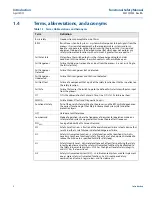
Страница 5: ...ied out by suitably qualified personnel 1 3 Safety messages Procedures and instructions in this section may require special precautions to ensure the safety of the personnel performing the operation Information that raises potential safety issues is indicated by a warning symbol Refer to the following safety messages before performing an operation preceded by this symbol Failure to follow these gu...

Страница 6: ...t an input from the process FIT FIT is the abbreviation for Failure In Time One FIT is 1x10 9 failure per hour FMEDA Failure Modes Effects and Diagnostic Analysis Functional Safety Part of the overall safety relating to the process and the BPCS which depends on the correct functioning of the Safety Instrumented System SIS and other protection layers HFT Hardware Fault Tolerance Low demand Mode of ...

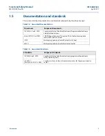
Страница 7: ...le Electronic Safety Related Systems Exida EM 10 08 36 R001 FMEDA Report Version V1 Revision R2 for the Mobrey magnetic level switch with a F84 Float IP101 Mobrey magnetic level switch Product Data Sheet M310 Mobrey magnetic level switch Instruction leaflet Table 1 3 Associated Standards Standards Purpose of standards IEC 61508 ed2 2010 Functional Safety of electrical electronic programmable elect...

Страница 8: ...4 Functional Safety Manual M310 FSM Rev BA Introduction April 2017 Introduction ...

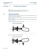
Страница 9: ...essel passes the level of the float the Switch Point When the process fluid level is below the Switch Point contacts B B are made and contacts A A are open Figure 2 1 on page 5 When the process fluid level is above the Switch Point contacts A A are made and contacts B B are open Figure 2 2 on page 5 Figure 2 1 Level Decreases Float Pivots Downwards Figure 2 2 Level Increases Float Pivots Upwards s...

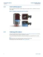
Страница 10: ...Example High and Low Level Alarm 2 3 Ordering information Level switch models fitted with options listed Appendix B Level Switches Certified to IEC 61508 of this manual have been externally assessed and certified to IEC 61508 A copy of the third party SIL certificate can be ordered using the part number MBY CERT SIL L2049 Note For all product information and documentation downloads see the on line...

Страница 11: ... If the level switch is used outside the application limits or with incompatible materials the reliability data and predicted SIL capability becomes invalid The construction materials of a level switch are specified in the product data sheet and the product reference manual see Table 1 2 on page 3 Use the model code on the product label and the ordering information table and specification in these...

Страница 12: ...c errors of design by the manufacturer A Safety Instrumented Function SIF designed with the Mobrey level switch must not be used at a SIL higher than the statement without prior use justification by the end user or verification of diverse technology in the design 3 5 2 Random integrity The Mobrey level switch is a type A device according to Table 2 of the standard IEC 61508 2 Using Route 2H assess...

Страница 13: ...luding the Mobrey level switch must be operational before process start up The user shall verify that the Mobrey level switch is suitable for use in safety applications by confirming the level switch nameplate and model number are properly marked Personnel performing maintenance and testing on the Mobrey level switch shall first be assessed as being competent to do so Results from periodic proof t...

Страница 14: ...10 Functional Safety Manual M310 FSM Rev BA Designing a Safety Function Using the Level Switch April 2017 Designing a Safety Function Using the Level Switch ...

Страница 15: ...not exceed the ratings in the specification section The Mobrey level switch must be accessible for physical inspection 4 2 Physical location and placement The Mobrey level switch shall be accessible with sufficient room for cover removal and electrical connections and allow for manual proof testing to take place The switch point is determined by the location of the level switch and consideration m...

Страница 16: ...12 Functional Safety Manual M310 FSM Rev BA Installation and Commissioning April 2017 Installation and Commissioning ...

Страница 17: ...mented and reported to Emerson using the contact details on the back page of this functional safety manual This is an important part of Emerson s SIS management process 5 4 Useful lifetime According to the Section 7 4 9 5 of IEC 61508 2 a useful lifetime based on experience should be assumed Although a constant failure rate is assumed by the probabilistic estimation method see FMEDA report this on...

Страница 18: ...14 Functional Safety Manual M310 FSM Rev BA Operation and Maintenance April 2017 Operation and Maintenance ...

Страница 19: ...alse trip 3 Disable any filling mechanism and drain the vessel to force the switch to the fail safe state and confirm that the Safe State was achieved and within the correct time INDEPENDENT PRECAUTIONS MUST BE TAKEN TO ENSURE THAT NO HAZARD CAN RESULT FROM THIS OPERATION 4 Reinstate the filling mechanism so that the vessel refills and confirm that the normal operating state of the switch was achi...

Страница 20: ...Proposed Proof test Procedure April 2017 Functional Safety Manual M310 Rev BA Proposed Proof test Procedure 16 ...

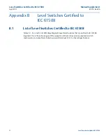
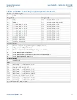
Страница 21: ...fied to IEC 61508 B 1 List of Level Switches Certified to IEC 61508 Tables B 1 B 2 and B 3 list all Mobrey Magnetic Level Switch options that are certified to IEC 61508 In general this is the entire range with the exception of the marine versions pneumatic switch mechanisms and some floats Refer to product data sheet IP101 for the full specifications ...

Страница 22: ... 436 EN 1092 1 PN 63 DN 125 429 EN 1092 1 PN 16 DN 80 437 EN 1092 1 PN 63 DN 150 430 EN 1092 1 PN 16 DN 100 Switch mechanism D Electrical 2 independent Single Pole Single Throw SPST contact sets P As Type D but with gold plated contacts D6 Electrical 2 independent circuits of double pole changeover contact sets P6 As Type D6 but with gold plated contacts H6 As Type D6 but with gold plated contacts...

Страница 23: ...old plated contacts Float F84 General purpose e g high low alarm 316 SST F93 Shrouded for dirty liquids 316 SST F185 General purpose e g high low alarm Alloy 400 F104 Cranked arm horizontal or vertical 316 SST Typical model number S 01 DB F84 Model Product description S Switch Flange head 250 Mobrey G 316 Stainless Steel 275 Mobrey G Gunmetal 256 3 in ASME B16 5 Class 150 RF 257 4 in ASME B16 5 Cl...

Страница 24: ... Type D6 but with gold plated contacts and hermetically sealed moving parts Enclosure Housing A Aluminum alloy G Gunmetal X Use AX or GX for applications with ambient temperatures 4 to 76 F 20 to 60 C Float F84 General purpose e g high low alarm 316 SST F185 General purpose e g high low alarm Alloy 400 F96 General purpose e g high low alarm 316 SST F98 General purpose e g high low alarm 316 SST F1...

Страница 25: ......

Страница 26: ...C Emerson com Linkedin com company Emerson Automation Solutions Twitter com Rosemount_News Facebook com Rosemount Youtube com user RosemountMeasurement Google com RosemountMeasurement Standard Terms and Conditions of Sale can be found on the Terms and Conditions of Sale page The Emerson logo is a trademark and service mark of Emerson Electric Co Mobrey is a trademark of Rosemount Measurement Ltd R...

Отзывы: