Chapter 6 Battery 65
NX UPS Single Module And Parallel System 250kVA ~ 800kVA User Manual
5. The bending radius of the cable shall be larger than 10D, where D is the outer diameter of the cable.
6. After cable connection, it is prohibited to pull the battery cables or the cable terminals.
7. Do not cross the battery cables during connection, and do not tie the battery cables together.
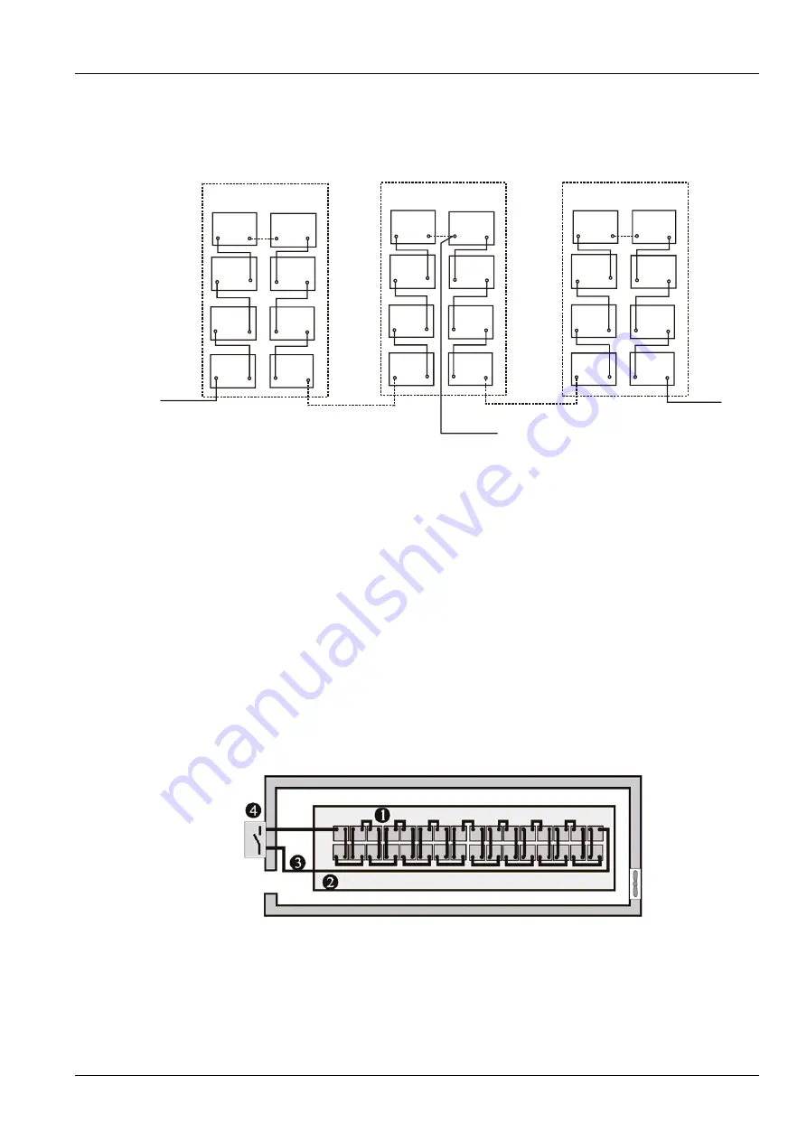
8. Refer to Figure 6-1 for the battery cable connection.
-
+
-
+
-
+
-
+
-
+
-
+
-
+
-
+
-
+
-
+
-
+
-
+
-
+
-
+
-
+
-
+
-
+
-
+
-
+
-
+
-
+
-
+
-
+
-
+
Top layer
Middle layer
Bottom layer
BCB-
BCB+
BCB-N
Figure 6-1 Battery cable connection
6.8 Battery Room Design
No matter which type of installation system is adopted, the following items shall be paid special attention to (refer to
Figure 6-2):
Layout of cells
No matter which battery installation system is used, the battery shall be located in a matter that it will not contact two
naked live parts with the potential difference over 150V at the same time. If it is unavoidable, insulated terminal shield
and insulated cable shall be used for the connection.
Workbench
The workbench (or pedal) must be skid-proof and insulated, and at least 1m wide.
Wiring
All the wiring distances shall be minimized.
BCB
The BCB is generally installed in the wall-mounted box near the battery.
Figure 6-2 Battery room design
6.9 BCB Box (Mandatory)
The UPS provides a BCB box as a mandatory part, which contains two BCBs and two BCB control boards, to provide
over discharge and overcurrent protections for the battery. The BCB box can also electrically isolate the UPS from the
battery to minimize the danger of the service personnel at work.
Содержание Liebert NX 0250kTK16FN01000
Страница 1: ...Liebert NX User Manual 250 800kVA UPS ...
Страница 2: ......
Страница 4: ......
Страница 14: ......


