Chapter 4 Operation And Display Panel 43
Liebert
®
ITA 16kVA And 20kVA UPS User Manual
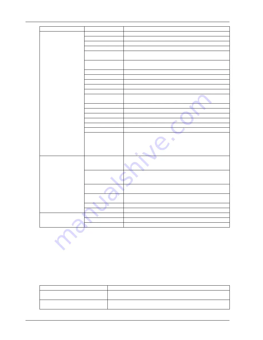
Menu Item
Explanation
Comm2 baud rate
For internal communication only, which cannot be set
Comm3 baud rate
Set the communication baud rate of the SNMP card port
Communication address
For RS485 communication
Single Group Batt Cap
Set the total battery capacity according to the configuration
Battery cells Number
Set the battery cell. Option: 30-cell, 32-cell, 34-cell, 36-cell, 38-cell,
40-cell
Equalize Charge
Allowed
Enabled or disabled
Temp Compensation
Enabled or disabled
Temp Sensor Position
Set the position of the temperature sensor
Shared Battery
Each UPS in parallel system shares the battery string or not
System Configuration
Set the UPS / parallel
Parallel Requisite Units
Set the parallel units
Parallel Redundant
units
Set the redundant units
ECO Mode
Set the operation mode. Option: Normal, ECO
Output Frequency Level
Set the output frequency
Output Voltage Level
Set the output voltage level
LBS Function
Set LBS function. Option: NONE, SLAVE or MASTER
Command password
You can change the command password. Default: ‘123456’
Protocol
Set the communication protocol of the UPS
Settings
3-in 3-out / 3-in 3-out
Set the output system: 3-in 3-out or 3-in 3-out
This setting can only be carried out after the EPO operation. After the
setting, you must power off the system, and confirm that the system
actual wiring mode complies with the setting. Power on the system
again, and the setting can take effect
Battery maintenance
test
The battery maintenance test will partly discharge the battery to get
rough assessment of the battery capacity. The load ranges from 20%
to 100%
Battery capacity test
The battery capacity test will completely discharge the battery to get
accurate assessment of the battery capacity. The load ranges from
20% to 100%
System test
The UPS self-test. The user starts this function, 5 seconds later, a pop
window will appear to show the test result
Stop testing
Manually stop the test, including the maintenance test, capacity test
and system test
Forcing charge
Manually conduct the battery forcing charge
Command
Stop forcing charge
Manually stop the battery forcing charge
Monitor version
Provide the monitor software version
Rectifier version
Provide the rectifier software version
Version
Inverter version
Provide the inverter software version
Keypad window
The function of the menu buttons (F1 ~ F4 and HELP) is shown in icon mode for the current display screen (see
Figure 4-4).
4.4 Prompt Window
A prompt window is displayed during the operation of the system to alert you to certain conditions and/or to require
your confirmation of a command or other operation. The prompts and meanings are given in Table 4-7.
Table 4-7 Prompts and meanings
Prompt Meaning
Transfer with interrupt, confirm or cancel
Inverter and bypass supplies are not synchronized, and the load transfer between
the bypass and inverter will cause a brief power supply interruption
This operation leads to output shutdown,
confirm or cancel
The bypass is abnormal, inverter shutdown will cause the load power-off


