Instruction Manual
D500242X012
A31A Cryogenic-Rotary Valve
February 2019
5
valve into the fully closed position. Then, take appropriate steps to ensure that the actuator does not cause the valve to
open during installation.
1. The A31A Cryogenic valve is normally shipped as part of an assembly with an actuator and other accessories. If the
valve and actuator have been purchased separately or if the actuator has been removed for maintenance, properly
mount the actuator and adjust valve/actuator travel and all travel stops before inserting the valve into the line.
Follow the instructions in this manual for Adjusting Travel stops. Also, refer to a separate actuator instruction manual
for detailed actuator mounting and adjustment procedures.
2. If not previously removed, remove the protective end covers from the valve and inspect the valve body to be certain
that it is free of foreign material. Also, be certain that adjacent pipelines are free of any foreign material, such as
pipe scale or welding slag that could damage the valve seating surfaces.
CAUTION
The A31A Cryogenic valve is designed for use with the appropriate piping schedule for the specified ANSI class. Minimum
inside diameters for flanges or pipe mating with valves are shown in tables 2 and 3. Be certain to align the valve accurately
to avoid contact between the disk and the flanges. Improper alignment or insufficient space for disk rotation could result in
damage to the disk.
Additionally, be certain that the valve body and any adjacent pipelines are free of foreign material, such as pipe scale or
welding slag that could damage the valve seating surfaces.
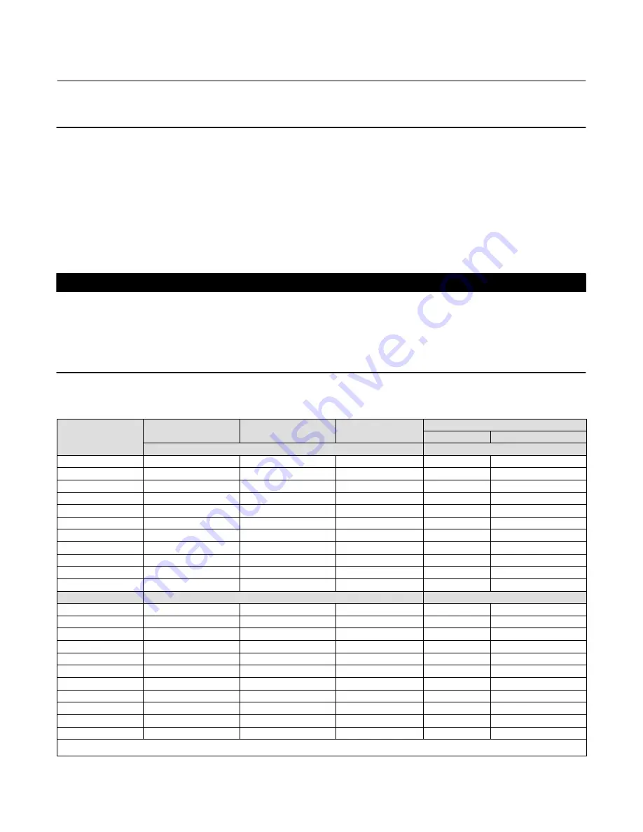
Table 2. Valve Body Data, Class 150
VALVE SIZE, INCHES
SHAFT DIAMETER AT
YOKE BEARING
FACE‐TO‐FACE DIMEN‐
SION
(1)
MINIMUM
I.D
.(2)
APPROXIMATE WEIGHT
Wafer
Single Flange
mm
Kilograms
3
16
47.6
71.4
12
16
4
19
54.0
93.7
21
22
6
25
57.2
147.6
24
28
8
25
63.5
196.9
34
40
10
32
71.4
254.0
57
67
12
38
81.0
298.5
74
93
14
30
92
330
87
120
16
32
102
378
133
182
18
38
114
429
170
231
20
44
127
470
210
302
24
57
154
575
326
455
Inches
Pounds
3
5/8
1‐7/8
2.81
27
36
4
3/4
2‐1/8
3.69
46
48
6
1
2‐1/4
5.81
53
61
8
1
2‐1/2
7.75
75
89
10
1‐1/4
2‐13/16
10.00
125
148
12
1‐1/2
3‐3/16
11.75
164
206
14
1‐3/16
3‐5/8
13
191
265
16
1‐1/4
4
14‐7/8
294
401
18
1‐1/2
4‐1/2
16‐7/8
374
510
20
1‐3/4
5
18‐1/2
463
665
24
2‐1/4
6‐1/16
22‐5/8
719
1004
1. Face‐to‐face dimensions are in compliance with MSS SP68 and API 609 specifications.
2. Minimum I.D. is the minimum pipe or flange I.D. required for disk swing clearance.


