Instruction Manual
D200124X012
2500 and 2503 Controllers/Transmitters
June 2017
9
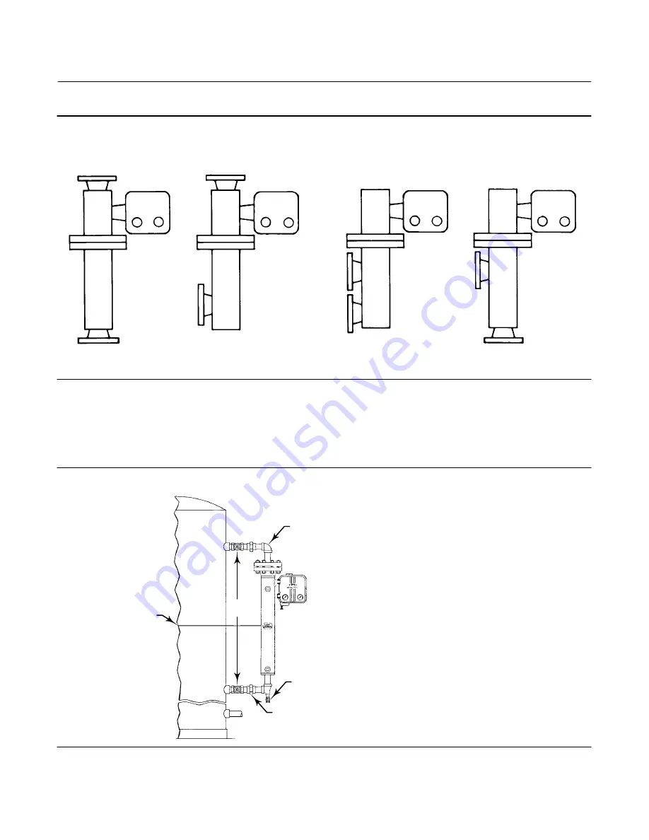
Figure 5. Cage Connection Styles
A1271-2
STYLE 1: TOP
AND BOTTOM
STYLE 2: TOP
AND LOWER SIDE
STYLE 3: UPPER
AND LOWER SIDE
STYLE 4: UPPER
SIDE AND BOTTOM
SCREWED: S3
FLANGED: F3
SCREWED: S2
FLANGED: F2
SCREWED: S1
FLANGED: F1
SCREWED: S4
FLANGED: F4
As shown in figure 6, mount the cage by running equalizing lines between the cage connections and the vessel. A
shutoff or hand valve with a 1‐1/2 inch diameter or larger port should be installed in each of the equalizing lines. Also
install a drain between the cage and shutoff or hand valve whenever the bottom cage line has a fluid‐trapping low
point.
Figure 6. Caged Sensor Mounting
EQUALIZING LINE
DRAIN VALVE
EQUALIZING LINE
CENTER OF LIQUID
OR INTERFACE LEVEL
DF5379‐A
A1883‐2
SHUTOFF
VALVES


