


62 Chapter 5 Parameter Introductions
EV2000 Series Universal Variable Speed Drive User Manual
EV2000
U
V
W
PE
M
X1
X2
COM
FWD
COM
R
S
T
3-phase
AC
supply
QF
.
.
.
.
.
.
X3
REW
.
k1
k2
k3
k4
k5
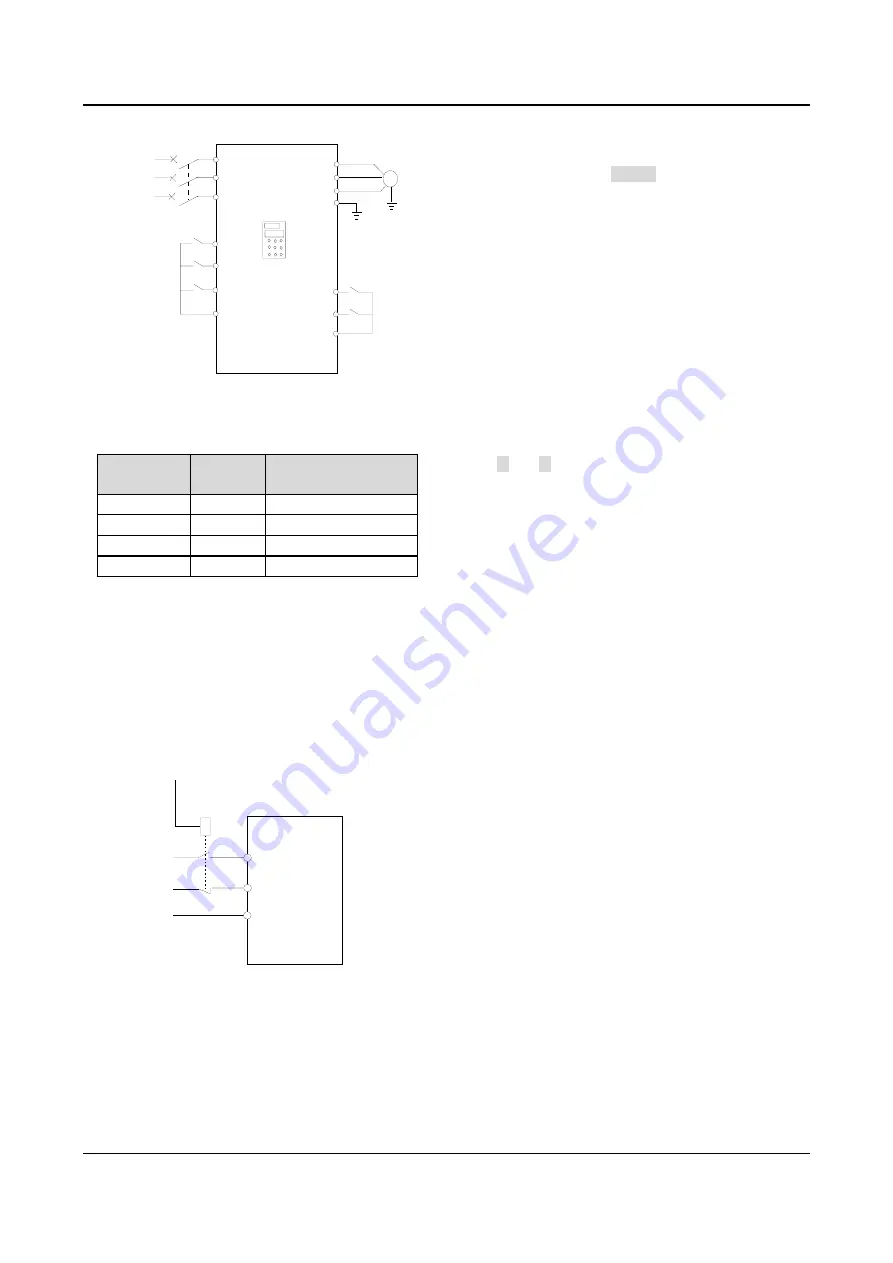
Fig. 5-40 Wiring for multi-speed operation
4~5: selecting Acc/Dec time
Table 5-7 Acc/Dec time selection
Terminal 2 Terminal 1
Acc/Dec time
selection
OFF
OFF
Acc time 1/Dec time 1
OFF
ON
Acc time 2/Dec time 2
ON
OFF
Acc time 3/Dec time 3
ON
ON
Acc time 4/Dec time 4
Through the On/Off combinations of terminals, Acc/Dec
time 1~4 can be selected.
6~7: inputting external fault signal (normally-open/close
input)
If the setting is 6~7, the fault signal of external
equipment can be input via the terminal, which is
convenient for the drive to monitor the external
equipment. Once the drive receives the fault signal, it
will display “E015”. The fault signal has two inputting
modes: normally-open and normally-close input.
X5
X6
COM
KM
EV2000
·
·
·
Fig. 5-41 Normally-open/close input
As shown in Fig. 5-41, X
5
is normally-open contact and
X
6
is normally-close command. KM is the relay for
inputting external fault signal.
8: inputting external reset signal
If the setting is 8, the drive can be reset via this terminal
when the drive has a fault. The function of this terminal
is the same with that of RESET on the panel.
9~10: inputting jog operation signal (JOGF/JOGR)
If the setting is 9~10, this terminal can enable jog
operation. JOGF is for inputting forward jog command
and JOGR is for reverse jog command. Jog frequency,
interval and Acc/Dec time of jog operation are defined in
F3.13~F3.16.
11: Coast-to-stop
If the setting is 11, the function of the terminal is the
same with that defined by F2.08. It is convenient for
remote control.
12~13: Frequency ramp UP/DN
If the setting is 12~13, the terminal can be used to
increase or decrease frequency. Its function is the same
with
c
and
d
keys on the panel, which enables remote
control. This terminal is enabled when F0.00=1 or
F9.01=2. Increase or decrease rate is determined by
F7.09.
14: pausing PLC operation:
If the setting is 14, the terminal is used to pause the PLC
operation and the drive operates at zero frequency when
the terminal is enabled. There is no timing of PLC
operation. If the terminal is disabled, the drive will start
on the fly and continue the PLC operation. Refer
F4.00~F4.14 to how to use this terminal.
15: Acc/Dec prohibiting command
If the setting is 15, the terminal can make the motor
operate at present speed without being influenced by
external signal (except stopping command).
Note:
This terminal is disabled in normal Dec-to-stop process.
16: 3-wire operation control.
Refer to F7.08, operation mode 2 and 3 (3-wire
operation mode 1 and 2).
17~18: inputting external stopping signal
(Normally-open/close input)
During operating, the drive stops its output and operates
at zero frequency when it receives external STOP signal.
Once the signal is removed, the drive will start on the fly
and resume normal operation.
There are two inputting modes of external stopping
signal: normally-open and normally-close input. As
shown in Fig. 5-41, X
5
is normally-open contact and X
6
is normally-close contact.