Proprietary and confidential
– Do not copy or distribute without permission from Emerson Climate Technologies GmbH
12/42
Technical Information
4.3
Inputs/outputs
4.3.1 Relay outputs
All relay outputs are potential-free normally open contacts with "RAST 5" connectors. The connections are
listed in Table 1 "Connector assignment".
The relays 6, 7, 8 and the alarm relay are additionally actuated by a watchdog timer. In the event of a micro
controller fault, these relays are deenergized after approx. 1s preventing any unsafe working condition of the
cabinet.
To avoid wiring errors, coding on the individual connectors ensures that they can only be connected to their
matching partner.
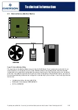
4.3.2 Display unit
Only the corresponding Emerson temperature display module is supported (ECD-05). An Emerson specific
short-circuit proof 1-bit bus is used as the transmission protocol.
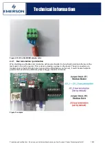
4.3.3 Digital inputs
Two digital inputs are provided on RAST 5 connector strips. (J23 / J24)
The digital inputs are active inputs and can be powered by 24 V to 230 V (AC/DC). Coding on the individual
connectors ensures that they can only be connected to their matching partner. This helps avoid any wiring
errors.
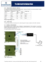
4.3.4 Compressor safety chain for high and low pressure switches
The safety chain internally operates at 24 V DC. The outputs are short-circuit proof. If the safety chain is closed,
both green LEDs on the inputs for high and low pressure switches are illuminated and the safety relay is closed.
Additionally, the safety chain is controlled by a watchdog timer. In case of an internal fault of the microprocessor
the safety relay is switched of automatically.
Figure 7: Safety Concept

