Proprietary and confidential
– Do not copy or distribute without permission from Emerson Climate Technologies GmbH
9/42
Technical Information
4.1.3 High and low pressure switches
The PCB has inputs for high and low pressure switches. The state of the LED concerned as well as the safety
relay status are indicated by the following table.
High pressure
switch
Low pressure
switch
High
pressure
LED
Low
pressure
LED
Safety relay
closed
closed
on
on
closed
closed
open
on
off
open
open
closed
off
off
open
open
open
off
off
open
Table 2: Logic safety chain
4.1.4 Alarm relay
The alarm relay operates in a fail safe mode. If no alarm is triggered, the relay is activated and the LED is illuminated.
4.2
Modbus communication
All configuration on the controller is done via Modbus / Monitoring System. If the controller is connected to
Modbus communication, activity is indicated by the green LED next to the micro controller. A receiving data
status is indicated by a flashing LED.
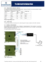
The principle setup is shown in the next picture:
Figure 3 Modbus wiring

