1598013141 XM664K GB CLABO rev1.2 2012.01.26
XM664K
5/6
ALC
Ab
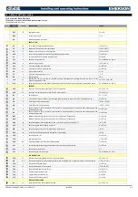
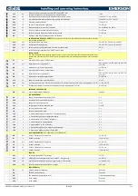
Alarms: rE=relating to temperature set point [SET+ALU] and [SET-ALL];
Ab= absolute value ALU or ALL within scale limits of selected sensor
rE; Ab
ALU
60
High temperature alarm threshold generating HA message after Ald minutes.
[0.0 to 50.0°C or ALL to 150.0°]
ALL
-50
Low temperature alarm threshold generating LA message after Ald minutes.
[0.0 to 50.0°C or -55.0°C to ALU]
AHy
2
Temperature alarms differential
[0.1 to 25.5°C]
ALd
15
HA and LA temperature alarm signal delay
0 to 255 min
dAo
1.3
Alarm signal delay at hour switch-on.10 minutes.
0.0 to 24h00min, res. 10 min
EdA
30
Exclusion of temperature alarm after defrost in minutes.
0 to 255 min
dot
30
Duration of exclusion of temperature alarm after door closing.
0 to 255 min
tbA
n
Silencing of alarm relay by pressing any key on the keyboard.
n; Y
CONFIGURATION OF RELAY OUTPUTS: Cpr=cold output, dEF=defrost, dF2=defrost2 FAn=fans, ALr=alarm, LiG=light,
AUS=auxiliary, OnF=ON/OFF
oA2
dEF
Configuration of 2nd relay function
CPr; dEF; dF2; FAn; ALr; LiG; AUS; OnF
oA5
dF2
Configuration of 5th relay function
CPr; dEF; dF2; FAn; ALr; LiG; AUS; OnF
AOP
oP
Relay output polarity configured as alarm. OP= alarm with open contact.
OP; CL
iAU
n
Auxiliary relay output independent from ON/OFF status of board.
n; Y
DIGITAL INPUTS
Key: EAL=external alarm, Bal=regulation block alarm, PAL=do not use, dor=door switch, dEF=external defrost contact, AUS=
auxiliary relay, LiG=light relay, OnF= On/OFF board, ES=energy saving, AtA=alternative map activation CbL= compressor
block
i1P
CL
Input polarity DI1 CL=active for closed contact
OP; CL
i1F
dor
Digital input function configuration DI1
EAL; bAL; PAL; dor; dEF; AUS; LiG; OnF; ES;
ATA; CbL
d1d
0
Alarm delay for configurable digital input DI1
0 to 255 min
i2P
CL
Input polarity DI2 CL=active for closed contact
OP; CL
i2F
AtA
Digital input function configuration DI2
EAL; bAL; PAL; dor; dEF; AUS; LiG; OnF; ES;
ATA; CbL
d2d
0
Alarm delay for configurable digital input DI2
0 to 255 min
nPS
10
Number of interventions at status before block
0 to 15
OdC
FAn
Loads control with door open: Fan=fans, Cpr=compressor, F-C fans and compressor. Valid if one of the parameters i1,2F= dor no; FAn; CPr; F-C
rrd
30
Forcing of fan compressor restart after door opening Valid if one of the parameters i1,2F= dor
0 to 255 min
KEYBOARD CONFIGURATION
bbC
6bb
6-key or 8-key keyboard configuration
6bb; 8bb
LAN MANAGEMENT
rdA
y
Remote function management activation (RVD)
n; Y
SEb
y
Sections that can be selected from keyboard
n; Y
LSn
- - -
Number of devices detected in LAN
1 to 8
LAn
- - -
Serial addresses of devices detected in LAN
1 to 247
L1d
y
Defrost 1 synchronisation in LAN
n; Y
L2d
y
Defrost 2 synchronisation in LAN
n; Y
LSP
n
Y= forcing of same set point for all boards, n= independent set point.
n; Y
LdS
n
Y= Synchronise board display n= independent display.
n; Y
LOF
n
Y= Synchronise ON/OFF n= ON/OFF independent
n; Y
LLi
y
Y= Synchronise Light n= Light independent
n; Y
LAU
n
Y= Synchronise AUX n= AUX independent
n; Y
LES
n
Y= Synchronise Energy Saving n= Energy Saving independent
n; Y
LSd
n
Y= Remote probe display n= no remote probe display
n; Y
INPUT CONFIGURATION. NTC (10K
Ω at
25°C), Ptc (806
Ω at 0°C)
P1C
Ntc
Probe P1 Configuration nP= not present
nP; PtC; ntC
Ot
0
Probe P1 calibration
[-12.0 to 12.0°C]
P2C
Ntc
Probe P2 Configuration nP= not present
nP; PtC; ntC
oE
0
Probe P2 calibration
[-12.0 to 12.0°C]
P3C
nP
Probe P3 Configuration nP= not present
nP - Ptc - ntc
O3
0
Probe P3 calibration
[-12.0 to 12.0°C]
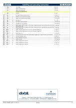
SERVICE
Adr
1
Cold output opening ON/OFF percentage
1 to 247
OnF
OFF
ON/OFF key function configuration (not used – ON/OFF – Energy saving)
nu; OFF; ES
LPC
LiG
Light key function configuration (not used – Light – auxiliary – FHU not used)
nu; LiG; AUS; FHU
dPC
dEF
Defrost key function configuration (defrost – auxiliary)
dEF; AUS
SERVICE DISPLAY
rEL
1.1
Firmware release code (read only)
Read only
Ptb
EEPROM map identification
Read only
Pr2
- - -
PR2 MENU input (protected parameters)
(Protected parameters input)
dP1
- - -
Probe 1 display
Read only
dP2
- - -
Probe 2 display
Read only

