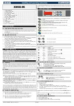

1598013141 XM664K GB CLABO rev1.2 2012.01.26
XM664K
3/6
11.
ALARMS
The alarm signals displayed on the keyboard can be divided into 2 groups:
1.
Local alarms, including all the alarms relating to the section directly controlled by the keyboard.
2.
Remote alarms, including all those alarms relating to the LAN.
The signal on the display remains until the alarm condition has ceased. All of the alarm signals flash, alternating
with the probe temperature, except for "P1" which is always flashing.
The "EE" alarm can be cancelled by pressing any key during the alarm signal. Then the message “rSt” is
displayed for about 3s before going back to normal functioning.
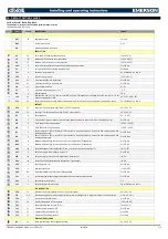
11.1
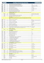
LOCAL ALARMS
Messagge
Cause
Outputs
PoF
Keyboard locked
Pon
Keyboard unlocked
rst
Alarm muting
noP
Probe not present
noL
Absence of communication keyboard-main unit
P1
Room probe failure
Compressor output acc. to par. Con
and CoF
P2
Evaporator probe failure
Outputs unchanged
P3
Auxiliary probe failure
Outputs unchanged
HA
Maximum temperature alarm
Outputs unchanged
LA
Minimum temperature alarm
Outputs unchanged
MSn
Serious alarm because of reaching the max
number of pauses
rtF
Real time clock board failure
Alarm output ON; other outputs
unchanged
rtc
Real time clock alarm
Outputs unchanged
EA
External alarm
Outputs unchanged
CA
Compressor alarm
Regulation outputs deactivated
PAL
Pressure sensor alarm
dA
Door open alarm
StP
Stop regulation
EE
Eeprom failure
11.2
REMOTE ALARMS
Mess.
Cause
“ASn”
Section n is in alarm, with n = serial LAN address ("LAN" parameter). this alarm is displayed only if
the keyboard is in “ALL” mode. This is a generic indication of the state of alarm. To have more
detailed information, set the keyboard so that it controls that specific section.
“nLn”
No link alarm (no communication) with section n (“Lan” parameter)
“nLn”
No link alarm (no communication) while a remote probe is viewed. This alarm appears only if the
LdS parameter of the section is set at "y".
“rPE”
Remote viewer error. More than one keyboard has been set for remote control
11.3
BUZZER SILENCING AND ALARM EXIT
Once the alarm signal has been detected, the buzzer and alarm exit can be deactivated by pressing any key.
However the signal on the display remains until the alarm condition has ceased. It is possible to inhibit the alarm
relay deactivation by setting the parameter tbA=n. In this way the alarm relay remains active as long as the
alarm condition lasts.
The signal buzzer is found in the keyboard T640.
11.4
“EE” ALARM
The instruments of the Dixell series are equipped with an internal control which checks the integrity of the data.
The flashing “EE” alarm which alternates with the temperature signals the presence of a data anomaly. .
11.5
MODE FOR CEASING ALARMS
The probe alarms “P1”, “P2” and “P3” are triggered about 10 sec after the probe failure. They automatically
cease 10 sec after the probe goes back to regular functioning. Before replacing a probe, it is recommended to
check the connections.
The temperature probes “HA” and “LA” automatically cease as soon as the thermostat temperature goes back
to normal, when defrost starts or when the door opens.
The No link alarms “nLn” and “nLn” cease automatically as soon as correct communication is re-established
between the sections
The digital input alarms “EAL” and “BAL” cease automatically when the input is deactivated.
12.
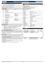
TECHNICAL DATA
Keyboard
Housing: self extinguishing ABS.
Case: facia 38x185 mm; depth 23mm.
Mounting: panel mounting in a 150x31 mm panel cut-out with two screws.
3 x 2mm.
Distance between the holes 165mm.
Frontal protection: IP65 with frontal gasket mod RG-L (optional).
Connections: Screw terminal block
2.5 mm
2
heat-resistant wiring.
Power supply: from XM664K power module
.
Display: 3 digits, red LED, 14.2 mm high.
Optional output: buzzer.
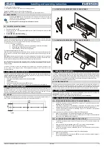
Mounting
Din
Housing
self extinguishing ABS
Dimensions
8 Din
Connections
Screw
1,6mm
2
and FASTON 6,3mm
Power Supply
230Vac
10%
Power absorption
9VA max.
Display
NO
Temperature inputs
3 sensors: NTC (10K
Ω a
t 25°C); PTC (806
Ω a
t 0°C)
-40 to +150°C; Pt1000 sensor
Digital inputs
Two free voltage digital inputs
Relay outputs
SPST 20 (8) A
Relay Defrost 1
SPST 8 (3) A
Relay Defrost 2
SPST 8 (3) A
Relay Fans
SPST 8 (3) A
Relay Light
SPDT 16 (5) A
Relay ON/OFF
SPDT 16 (5) A
Data storing
On the non-volatile memory (EEPROM)
Kind of action
1B
Pollution degree
Normal
Software class
A
Operating temperature
0 to 60°C
Storage temperature
-25 to 60°C
Relative humidity
20 to 85% (not condensing)
Measuring and regulation range
NTC probe: -40 to 110°C
PTC probe: -50 to 150°C
Resolution
0.1°C
Accuracy
±0.5°C ±1 digit
13.
CONNECTIONS


