AE4-1322
© 2002 Copeland Corporation
Issued 4-2002
Printed in U.S.A.
16
6.2 Selection of electrical components
6.2 Selection of electrical components
6.2 Selection of electrical components
6.2 Selection of electrical components
6.2 Selection of electrical components
Cables, contractors and fuses
Cables, contractors and fuses
Cables, contractors and fuses
Cables, contractors and fuses
Cables, contractors and fuses
CAUTION
CAUTION
CAUTION
CAUTION
CAUTION
Nominal power is not the same as
Nominal power is not the same as
Nominal power is not the same as
Nominal power is not the same as
Nominal power is not the same as
maximum motor power! When selecting
maximum motor power! When selecting
maximum motor power! When selecting
maximum motor power! When selecting
maximum motor power! When selecting
cables, contactors and fuses:
cables, contactors and fuses:
cables, contactors and fuses:
cables, contactors and fuses:
cables, contactors and fuses: Maximum
Maximum
Maximum
Maximum
Maximum
operating current / maximum motor
operating current / maximum motor
operating current / maximum motor
operating current / maximum motor
operating current / maximum motor
power must be considered. See chapter 8.
power must be considered. See chapter 8.
power must be considered. See chapter 8.
power must be considered. See chapter 8.
power must be considered. See chapter 8.
Contactor selection: according to
Contactor selection: according to
Contactor selection: according to
Contactor selection: according to
Contactor selection: according to
operational category
operational category
operational category
operational category
operational category AC 3.
AC 3.
AC 3.
AC 3.
AC 3.
Part winding motors
Part winding motors
Part winding motors
Part winding motors
Part winding motors
The following current values appear in the part wind-
ings:
PW1
PW2
50%
50%
Both of the contactors should be selected for at least
60% of the maximum operating current.
Star delta motors
Star delta motors
Star delta motors
Star delta motors
Star delta motors
Calculate mains and delta contactor each to at least
60%, start contactor to 33% of the maximum operating
current.
Power factor correction
Power factor correction
Power factor correction
Power factor correction
Power factor correction
For the reduction of the reactive current when using
inductive loads (motors, transformers), power factor
correction systems (capacitors) are increasingly being
used. However, apart from the undisputed power
supply advantages, experience shows that the layout
and execution of such systems is not a simple matter,
as insulation damage on motors and increased contact
arcing on contactors can occur.
With a view to a safe operating mode, the correction
system should be designed to effectively prevent “over-
correction” in all operating conditions and the uncon-
trolled discharge of the capacitors when starting and
shutting down the motors.
General design criteria
General design criteria
General design criteria
General design criteria
General design criteria
•
Maximum power factor (P.F. 0.95 - taking into
consideration all load conditions.)
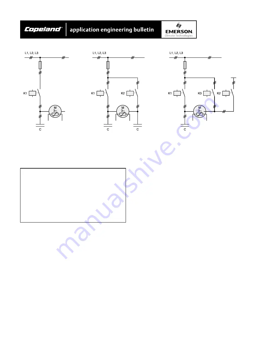
Individual correction (Fig. 21)
Individual correction (Fig. 21)
Individual correction (Fig. 21)
Individual correction (Fig. 21)
Individual correction (Fig. 21)
•
With capacitors that are directly fitted to the motor
(without the possibility of switching off with
contactors), the capacitor capacity must never be
greater than 90% of the zero-load reactive capacity
of the motor (less than 25% of max. motor power).
With higher capacities there is the danger of self-
exiting when shutting off, resulting in damage to the
motor.
Figure 18
Power factor correction on individual compressors


