


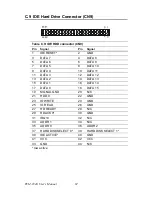
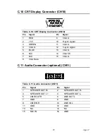

TPC-642 User’s Manual
78
Appendix A Programming the Watchdog
Timer
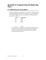
A.1 Supported Input Timing Modes
In order to program the watchdog timer, you must write a program which
writes I/O port address 443 (hex). The output data is a value of time inter-
val. The value range is from 01 (hex) to 3E (hex), and the related time
interval is 1 sec. to 62 sec.
Data
Time Interval
01
1 sec.
02
2 sec.
03
3 sec.
04
4 sec.
.
.
.
3E
62 sec.
After data entry, your program must refresh the watchdog timer by
rewriting the I/O port 443 (hex) while simultaneously setting it.
When you want to disable the watchdog timer, your program
should read I/O port 443 (hex).
Содержание PCM-9340F-0CA1
Страница 1: ...i PCM 9340 ISA STPC Elite 133 SBC with CPU 32MB SDRAM VGA LCD LAN DOC PC104 Users Manual...
Страница 4: ...PCM 9340 User s Manual iv...
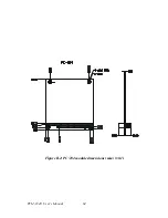
Страница 14: ...PCM 9340 User s Manual 6 1 4 Board layout dimensions Figure 1 1 Board layout dimensions...
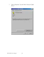
Страница 48: ...PCM 9340 User s Manual 40 2 Select the Settings tab then click the Advanced Properties but ton...
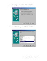
Страница 49: ...41 Chapter 4 SVGA Setup 3 Choose the Adapter tab then press the Change button 4 Press the Have Disk button...
Страница 53: ...45 Chapter 4 SVGA Setup 2 Select Adapter then Change...
Страница 54: ...PCM 9340 User s Manual 46 3 Select Display a list of all and press Next 4 Press the Have disk button...
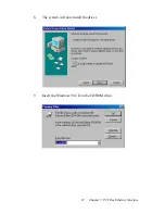
Страница 58: ...PCM 9340 User s Manual 50 2 Choose the Settings tab and press the Display Type button...
Страница 59: ...51 Chapter 4 SVGA Setup 3 Press the Change button...
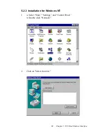
Страница 66: ...PCM 9340 User s Manual 58 2 Click Device Manager folder then double click PCI Ethernet Controller...
Страница 67: ...59 Chapter 5 PCI Bus Ethernet Interface 3 Select the Driver tab then click Update Driver...
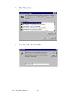
Страница 71: ...63 Chapter 5 PCI Bus Ethernet Interface 2 Click the Device Manager tab then highlight PCI Ethernet Con troller...
Страница 72: ...PCM 9340 User s Manual 64 3 Click on Properties select the Driver tab then Update Driver...
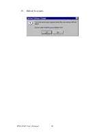
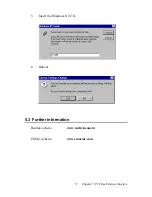
Страница 76: ...PCM 9340 User s Manual 68 10 Reboot the system...
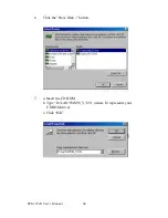
Страница 78: ...PCM 9340 User s Manual 70 3 Click Have Disk 4 Type in the path then click OK...
Страница 80: ...PCM 9340 User s Manual 72...
Страница 88: ...TPC 642 User s Manual 80...
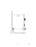
Страница 91: ...83 Appx B Figure B 1 PC 104 module mounting diagram PCM 9340...
Страница 92: ...PCM 9340 User s Manual 84 Figure B 2 PC 104 module dimensions mm 0 1...
Страница 115: ...107 Appx E E Mechanical Drawings Appendix...
Страница 116: ...PCM 9340 User s Manual 108 E 1 Mechanical Drawings Figure E 1 Mechanical Drawing component side...
Страница 117: ...109 Appx E Figure E 2 PCM 9340 Mechanical Drawing solder side...
Страница 118: ...PCM 9340 User s Manual 110...