


vi
2.14
IR connector (CN8)......................................................... 18
2.15
Enhanced IDE HDD Connector (CN9)........................... 18
2.16
VGA interface connections (CN10, CN15, CN19)......... 18
2.16.1 CRT display connector (CN10) .................................... 18
2.16.2 Extension flat panel connector (CN15) ........................ 19
2.16.3 Flat panel display connector (CN19) ............................ 19
2.17
Audio interfaces (CN11, CN17) (optional)..................... 19
2.17.1 Audio connector (CN11) .............................................. 19
2.17.2 CD audio input connector (CN17)................................ 19
2.17.3 Audio power source setting (JP7)................................. 19
2.18
ATX power (CN13, CN16, CN22) ................................. 21
Figure 2.3:Wiring for ATX feature power.................... 21
2.18.1 ATX feature connector (CN13) .................................... 21
2.18.2 Board Main Power (CN16)........................................... 21
2.18.3 ATX soft power switch (CN22).................................... 21
2.19
FDD connector (CN14)................................................... 22
2.20
Parallel port connector (CN18) ....................................... 22
2.21
General Purpose Input Output (CN20)............................ 22
Chapter
3 Award BIOS Setup.........................................23
3.1
System test and initialization........................................... 24
3.1.1
System configuration verification................................. 24
3.2
Award BIOS setup .......................................................... 25
3.2.1
Entering setup .............................................................. 25
Figure 3.1:BIOS setup program initial screen .............. 25
3.2.2
Standard CMOS Features setup.................................... 26
Figure 3.2:CMOS Features setup.................................. 26
3.2.3
Advanced BIOS Features setup .................................... 27
Figure 3.3:Advanced BIOS Features setup................... 27
3.2.4
Advanced Chipset Features setup ................................. 28
Figure 3.4:Advanced Chipset Features setup ............... 28
3.2.5
Integrated Peripherals ................................................... 29
Figure 3.5:Integrated Peripherals.................................. 29
3.2.6
Power Management Setup ............................................ 30
Figure 3.6:Power Management Setup........................... 30
3.2.7
PnP/PCI Configurations................................................ 31
Figure 3.7:PnP/PCI Configurations .............................. 31
3.2.8
Load Optimized Defaults.............................................. 32
Figure 3.8:Load BIOS defaults screen.......................... 32
3.2.9
Set Password ................................................................. 32
Figure 3.9:Set Password ............................................... 34
3.2.10 Save & Exit Setup......................................................... 35
Figure 3.10:Save and Exit Setup................................... 35
3.2.11 Exit Without Saving...................................................... 36
Figure 3.11:Exit without Saving................................... 36
Содержание PCM-9340F-0CA1
Страница 1: ...i PCM 9340 ISA STPC Elite 133 SBC with CPU 32MB SDRAM VGA LCD LAN DOC PC104 Users Manual...
Страница 4: ...PCM 9340 User s Manual iv...
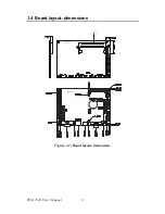
Страница 14: ...PCM 9340 User s Manual 6 1 4 Board layout dimensions Figure 1 1 Board layout dimensions...
Страница 48: ...PCM 9340 User s Manual 40 2 Select the Settings tab then click the Advanced Properties but ton...
Страница 49: ...41 Chapter 4 SVGA Setup 3 Choose the Adapter tab then press the Change button 4 Press the Have Disk button...
Страница 53: ...45 Chapter 4 SVGA Setup 2 Select Adapter then Change...
Страница 54: ...PCM 9340 User s Manual 46 3 Select Display a list of all and press Next 4 Press the Have disk button...
Страница 58: ...PCM 9340 User s Manual 50 2 Choose the Settings tab and press the Display Type button...
Страница 59: ...51 Chapter 4 SVGA Setup 3 Press the Change button...
Страница 66: ...PCM 9340 User s Manual 58 2 Click Device Manager folder then double click PCI Ethernet Controller...
Страница 67: ...59 Chapter 5 PCI Bus Ethernet Interface 3 Select the Driver tab then click Update Driver...
Страница 71: ...63 Chapter 5 PCI Bus Ethernet Interface 2 Click the Device Manager tab then highlight PCI Ethernet Con troller...
Страница 72: ...PCM 9340 User s Manual 64 3 Click on Properties select the Driver tab then Update Driver...
Страница 76: ...PCM 9340 User s Manual 68 10 Reboot the system...
Страница 78: ...PCM 9340 User s Manual 70 3 Click Have Disk 4 Type in the path then click OK...
Страница 80: ...PCM 9340 User s Manual 72...
Страница 88: ...TPC 642 User s Manual 80...
Страница 91: ...83 Appx B Figure B 1 PC 104 module mounting diagram PCM 9340...
Страница 92: ...PCM 9340 User s Manual 84 Figure B 2 PC 104 module dimensions mm 0 1...
Страница 115: ...107 Appx E E Mechanical Drawings Appendix...
Страница 116: ...PCM 9340 User s Manual 108 E 1 Mechanical Drawings Figure E 1 Mechanical Drawing component side...
Страница 117: ...109 Appx E Figure E 2 PCM 9340 Mechanical Drawing solder side...
Страница 118: ...PCM 9340 User s Manual 110...


