background image

29

Chapter 3  Award BIOS Setup

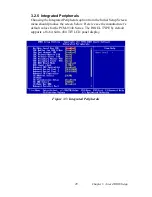
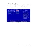
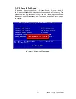
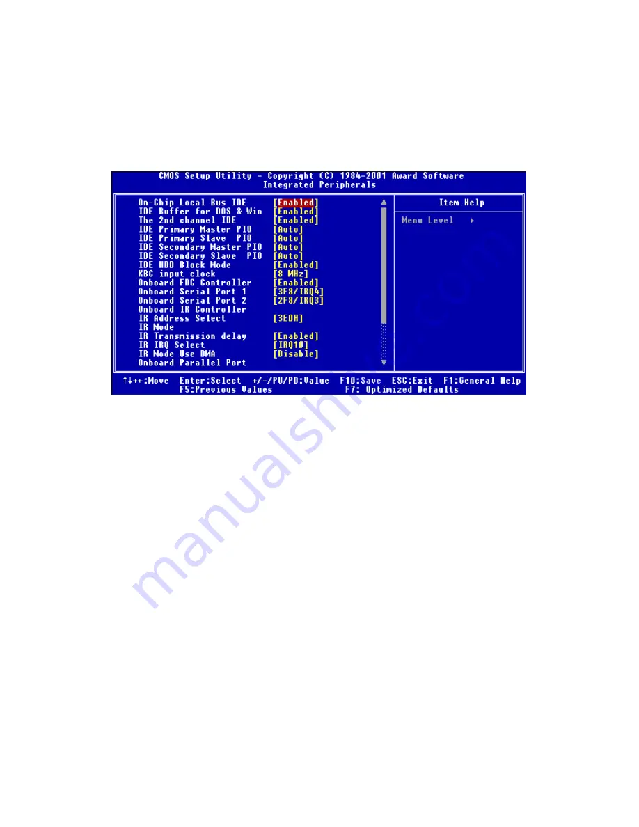
3.2.5  Integrated Peripherals

Choosing the Integrated Peripherals option from the Initial Setup Screen 
menu should produce the screen below.  Here we see the manufacturer’s 
default values for the PCM-9340 Series. The PANEL TYPE by default 
supports a 18-bit 640 x 480 TFT LCD panel display. 

Figure 3.5: Integrated Peripherals

Содержание PCM-9340F-0CA1

Страница 1: ...i PCM 9340 ISA STPC Elite 133 SBC with CPU 32MB SDRAM VGA LCD LAN DOC PC104 Users Manual...

Страница 2: ...ademark of Award Software International Inc VIA is a trademark of VIA Technologies Inc IBM PC AT PS 2 and VGA are trademarks of International Business Machines Corporation Intel and Pentium are tradem...

Страница 3: ...40504 1 keyboard mouse cable P N 1700060202 1 secondary serial port cable P N 1701140201 1 parallel cable P N 1700260250 1 floppy cable P N 1701340603 1 COM3 COM4 cable P N 1701200220 1 Mini Jumper pa...

Страница 4: ...PCM 9340 User s Manual iv...

Страница 5: ...tting Jumpers 9 2 2 COM2 Select JP2 10 2 3 Watchdog Timer Action JP3 10 2 4 DOC 2000 Address Setting JP4 11 2 5 Clear CMOS JP5 12 2 6 Audio Amp Power Select JP7 12 2 7 Connectors 13 2 7 1 Connector Lo...

Страница 6: ...3 Award BIOS Setup 23 3 1 System test and initialization 24 3 1 1 System configuration verification 24 3 2 Award BIOS setup 25 3 2 1 Entering setup 25 Figure 3 1 BIOS setup program initial screen 25...

Страница 7: ...tion for Windows 95 98 NT 75 Appendix A Programming the Watchdog Timer 77 A 1 Supported Input Timing Modes 78 Appendix B Installing PC 104 Modules 81 B 1 Installing PC 104 Modules 82 Figure B 1 PC 104...

Страница 8: ...Purpose Input Output CN20 99 C 21 Auxiliary power connector CN21 99 C 22 ATX Power Button CN22 99 C 23 Reset Button Connector SW1 100 Appendix D System Assignments 101 D 1 System I O Ports 102 D 2 DMA...

Страница 9: ...ral Information Chapter 1 General Information 1 General Information This chapter gives background information on the PCM 9340 Sections include Introduction Features Specifications Board layout and dim...

Страница 10: ...l ports three RS 232s and one RS 232 422 485 with DB 9 connectors and a mini DIN PS 2 keyboard mouse interface and an optional audio function An SVGA LCD display controller LCD and CRT displays allows...

Страница 11: ...n board 32 MB SDRAM On board VGA LCD display controller and supports DSTN TFT LCD 62 level watchdog timer jumperless on line setup supported Supports wake up on LAN ring on by Modem SSD supports DiskO...

Страница 12: ...ec Floppy disk drive interface Supports up to two FDDs 360 KB 1 2 MB 720 KB 1 44 MB 2 88 MB Parallel port One parallel port supports EPP ECP IR port One 115 Kbps IrDA compliant serial infrared Serial...

Страница 13: ...ddress switchless setting Built in boot ROM 1 3 4 Audio Interface optional Chipset Avance Logic ALS4000 PCI Interface Mic in Line in CD Audio in Line out speaker out 1 3 5 Mechanical and Environmental...

Страница 14: ...PCM 9340 User s Manual 6 1 4 Board layout dimensions Figure 1 1 Board layout dimensions...

Страница 15: ...erals switches and indicators to the PCM 9340 board It also covers jumper settings You can access most of the con nectors from the top of the board while it is installed in the chassis If you have a n...

Страница 16: ...40 User s Manual 8 Chapter 2 Installation 2 1 Jumpers The PCM 9340 has a number of jumpers that allow you to configure your system to suit your application 2 1 1 Jumper Locations Figure 2 1 Jumper Loc...

Страница 17: ...the clip Sometimes a jumper will have three pins labeled 1 2 and 3 In this case you would connect either pins 1 and 2 or 2 and 3 The jumper settings are schematically depicted in this manual as follo...

Страница 18: ...ning the control software refer to Appendix A When the watchdog timer activates CPU processing has come to a halt it can either reset the system or generate an interrupt on IRQ11 This choice for watch...

Страница 19: ...ting Pins Address 1 2 3 4 5 6 closed closed open CC000 CDFFF closed open closed D0000 D1FFF closed open open D4000 D5FFF open closed closed D8000 D9FFF open closed open DC000 DDFFF open open open OFF...

Страница 20: ...re clearing the CMOS Before turning the power supply back on return the jumper to 3 0 V Battery On Table 2 5 JP5 Clear CMOS Pins Function 1 2 clear CMOS 2 3 3 0 V battery on default setting clear CMOS...

Страница 21: ...Connecting Peripherals 2 7 Connectors Connectors on the board link it to external devices such as hard disk drives a keyboard or expansion bus connectors 2 7 1 Connector Locations Figure 2 2 Connecto...

Страница 22: ...IR connector infrared CN9 Hard disk connector CN10 CRT display connector CN11 Audio connector optional CN12 Backlight connector CN13 ATX feature connector CN14 Floppy disk connector CN15 Ext flat pane...

Страница 23: ...cation network 2 10 1 COM3 COM4 RS 232 port CN2 The COM3 COM4 series port consists of 20 pin dual in line male header Warning Always completely disconnect the power cord from your chassis whenever you...

Страница 24: ...system BIOS setup The table below shows the settings for the PCM 9340 s serial ports COM1 4 can share one IRQ that can be selected in BIOS setup under Windows 98 and Windows NT Choices are IRQ3 IRQ4...

Страница 25: ...ed the green lamp is activated Note polarity on LEDs Power and HDD LED LED2 LED 2 should be set so when the HDD is accessed the yellow lamp is activated and when the power is on the green lamp is acti...

Страница 26: ...e just one drive you should set it as the master See the documenta tion that came with your drive for more information Connect the first hard drive to the free end of the cable Wire 1 on the cable sho...

Страница 27: ...he PCM 9340 is equipped with a high quality audio interface which provides 16 bit CD quality recording and playback as well as OPL3 com patible FM music It is supported by all major operating systems...

Страница 28: ...setting Configuration of the audio interface may be done entirely via the soft ware utility You do not have to set any jumpers if you don t want to Refer to Chapter 6 for audio setup details Table 2...

Страница 29: ...ture connector CN13 Connect the tiny 2 wire plug to CN13 ATX feature connector 2 18 2 Board Main Power CN16 Connect the 4 wire plug to CN16 2 18 3 ATX soft power switch CN22 Connect the power on off b...

Страница 30: ...card to a printer The PCM 9340 includes an on board parallel port accessed through a 26 pin flat cable connector CN18 The card comes with an adapter cable which lets you use a traditional DB 25 con n...

Страница 31: ...23 Chapter 3 Award BIOS Setup Chapter 4 Award BIOS Setup 3 Award BIOS Setup This chapter describes how to set BIOS configuration data CHAPTER...

Страница 32: ...ce 3 1 1 System configuration verification These routines check the current system configuration against the values stored in the board s CMOS memory If they do not match the program outputs an error...

Страница 33: ...modify the basic system configuration This type of information is stored in battery backed CMOS RAM so that it retains the Setup information when the power is turned off 3 2 1 Entering setup Power on...

Страница 34: ...tial Setup Screen menu the screen shown below is displayed This standard Setup Menu allows users to configure system components such as date time hard disk drive floppy drive and display Once a field...

Страница 35: ...ures setup By choosing the Advanced BIOS Features Setup option from the Initial Setup Screen menu the screen below is displayed This sample screen contains the manufacturer s default values for the PC...

Страница 36: ...ures setup By choosing the Advanced Chipset Features option from the Initial Setup Screen menu the screen below is displayed This sample screen contains the manufacturer s default values for the PCM 9...

Страница 37: ...tegrated Peripherals option from the Initial Setup Screen menu should produce the screen below Here we see the manufacturer s default values for the PCM 9340 Series The PANEL TYPE by default supports...

Страница 38: ...ement Setup By choosing the Power Management Setup option from the Initial Setup Screen menu the screen below is displayed This sample screen contains the manufacturer s default values for the PCM 934...

Страница 39: ...onfigurations By choosing the PnP PCI Configurations option from the Initial Setup Screen menu the screen below is displayed This sample screen contains the manufacturer s default values for the PCM 9...

Страница 40: ...1 Choose the Set Password option from the CMOS Setup Utility main menu and press Enter 2 When you see Enter Password enter the desired password and press Enter Figure 3 8 Load BIOS defaults screen Not...

Страница 41: ...from the CMOS Setup Utility main menu and press Enter 2 When you see Enter Password enter the existing password and press Enter 3 You will see Confirm Password Type it again and hit Enter 4 Select Set...

Страница 42: ...word enter the existing password and press Enter 3 You will see Confirm Password Type it again and hit Enter 4 Select Set Password again and at the Enter Password prompt don t enter anything just pres...

Страница 43: ...hen Enter the values entered in the setup utilities will be recorded in the chipset s CMOS memory The microprocessor checks this every time you turn your system on and uses the settings to configure t...

Страница 44: ...40 User s Manual 36 3 2 11 Exit Without Saving Selecting this option and pressing Enter lets you exit the Setup pro gram without recording any new values or changing old ones Figure 3 11 Exit without...

Страница 45: ...37 Chapter 4 SVGA Setup Chapter 5 PCI VGA Setup 4 SVGA Setup Introduction Installation of SVGA drivers for Windows 95 98 NT CHAPTER...

Страница 46: ...Multiple frequency multisync monitors are handled as if they were analog monitors 4 1 2 Display memory With 2MB shared memory the VGA controller can drive CRT displays or color panel displays with re...

Страница 47: ...39 Chapter 4 SVGA Setup 4 2 1 Installation for Windows 95 1 In the Windows 95 Main screen click on Start select Settings then Control Panel Double click the Display icon...

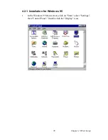
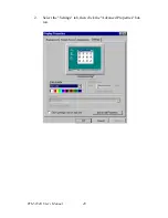
Страница 48: ...PCM 9340 User s Manual 40 2 Select the Settings tab then click the Advanced Properties but ton...

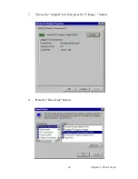
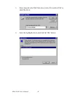
Страница 49: ...41 Chapter 4 SVGA Setup 3 Choose the Adapter tab then press the Change button 4 Press the Have Disk button...

Страница 50: ...PCM 9340 User s Manual 42 5 Direct the path to the SMI VGA driver in the CD and click OK to install the driver 6 Select the highlighted item and click the OK button D VGA WIN95...

Страница 51: ...43 Chapter 4 SVGA Setup 7 Silicon Motion LynxEM appears under the adapter tab Click the Apply button then the OK button 8 Press Yes to reboot...

Страница 52: ...PCM 9340 User s Manual 44 4 2 2 Installation for Windows 98 1 Select Start Settings Control Panel double click Display press Settings then press the Advanced button...

Страница 53: ...45 Chapter 4 SVGA Setup 2 Select Adapter then Change...

Страница 54: ...PCM 9340 User s Manual 46 3 Select Display a list of all and press Next 4 Press the Have disk button...

Страница 55: ...47 Chapter 4 SVGA Setup 5 Insert the CD into the CD ROM drive Type in the path to the CD ROM then press OK 6 Select the highlighted item then click OK D VGA WIN98...

Страница 56: ...PCM 9340 User s Manual 48 7 Silicon Motion LynxEM appears under the adapter tab Click the Apply button 8 Press Yes to reboot...

Страница 57: ...49 Chapter 4 SVGA Setup 4 2 3 Installation for Windows NT 1 Select Start Settings Control Panel and double click the Display icon...

Страница 58: ...PCM 9340 User s Manual 50 2 Choose the Settings tab and press the Display Type button...

Страница 59: ...51 Chapter 4 SVGA Setup 3 Press the Change button...

Страница 60: ...PCM 9340 User s Manual 52 4 Click the Have Disk button 5 Type the path to the CD ROM and press the OK button D VGA WIN_NT...

Страница 61: ...53 Chapter 4 SVGA Setup 6 Select the highlighted item and click the OK button 7 Press Yes to proceed 8 Press OK to reboot...

Страница 62: ...Information For further information about the AGP SVGA installation in your PCM 9340 including driver updates troubleshooting guides and FAQ lists visit the following web resources VIA website www vi...

Страница 63: ...Interface Chapter 7 PCI Bus Ethernet Interface 5 PCI Bus Ethernet Interface This chapter provides information on Ethernet configuration Introduction Installation of Ethernet drivers for Windows 95 98...

Страница 64: ...e utilized by incorporating the boot ROM image files for the appropriate network operating system The boot ROM BIOS files are combined with system BIOS which can be enabled dis abled in the BIOS setup...

Страница 65: ...57 Chapter 5 PCI Bus Ethernet Interface 5 2 1 Installation for Windows 95 1 a Select Start Settings Control Panel b Double click System...

Страница 66: ...PCM 9340 User s Manual 58 2 Click Device Manager folder then double click PCI Ethernet Controller...

Страница 67: ...59 Chapter 5 PCI Bus Ethernet Interface 3 Select the Driver tab then click Update Driver...

Страница 68: ...PCM 9340 User s Manual 60 4 Select No select driver from list and click the NEXT button 5 Highlight Network Adapters then click the NEXT button...

Страница 69: ...61 Chapter 5 PCI Bus Ethernet Interface 6 Click Have Disk to update the LAN driver 7 Direct the path to the LAN driver to install it 8 Insert the Windows 95 CD and click OK...

Страница 70: ...PCM 9340 User s Manual 62 9 Reboot the system 5 2 2 Installation for Windows 98 1 a Select Start Settings Control Panel b Double click on the System icon...

Страница 71: ...63 Chapter 5 PCI Bus Ethernet Interface 2 Click the Device Manager tab then highlight PCI Ethernet Con troller...

Страница 72: ...PCM 9340 User s Manual 64 3 Click on Properties select the Driver tab then Update Driver...

Страница 73: ...65 Chapter 5 PCI Bus Ethernet Interface 4 Select Display a list of all the then hit NEXT 5 Select Network adapters and click the NEXT button...

Страница 74: ...PCM 9340 User s Manual 66 6 Click the Have Disk button 7 a Insert the CD ROM b Type D LAN WIN98_V3 94 where D represents your CDROM drive c Click OK...

Страница 75: ...67 Chapter 5 PCI Bus Ethernet Interface 8 The system will now install the driver 9 Insert the Windows 98 CD in the CDROM drive...

Страница 76: ...PCM 9340 User s Manual 68 10 Reboot the system...

Страница 77: ...69 Chapter 5 PCI Bus Ethernet Interface 5 2 3 Installation for Windows NT 1 a Select Start Settings and Control Panel b Double click Network 2 Click on Select from list...

Страница 78: ...PCM 9340 User s Manual 70 3 Click Have Disk 4 Type in the path then click OK...

Страница 79: ...71 Chapter 5 PCI Bus Ethernet Interface 5 Insert the Windows NT CD 6 Reboot 5 3 Further information Realtek website www realtek com tw EMAC website www emacinc com...

Страница 80: ...PCM 9340 User s Manual 72...

Страница 81: ...apter 6 Audio Setup 6 Audio Setup The PCM 9340 is equipped with an audio interface that records and plays back CD quality audio This chapter provides instructions for installing the software drivers f...

Страница 82: ...hesizer is register compatible with the OPL3 and has extended capabilities 6 2 Audio Driver Installation Before installing the audio driver please take note of the procedures detailed below You must k...

Страница 83: ...on for Windows 95 98 NT 1 a Select Start Run b Type in the correct path D Biscuit 9340 Audio Winxx c Click the OK button 2 a Click Yes to accept the agreement b On the next page read the Readme file t...

Страница 84: ...PCM 9340 User s Manual 76 3 a Click Next to continue b Follow the procedure which appears on your screen 4 After installation select Yes and click Finish to restart the com puter...

Страница 85: ...g the Watchdog Timer The PCM 9340 is equipped with a watchdog timer that resets the CPU or generates an interrupt if processing comes to a standstill for any reason This feature ensures system reliabi...

Страница 86: ...tput data is a value of time inter val The value range is from 01 hex to 3E hex and the related time interval is 1 sec to 62 sec Data Time Interval 01 1 sec 02 2 sec 03 3 sec 04 4 sec 3E 62 sec After...

Страница 87: ...rt and restart the watchdog 30 GOSUB 1000 REM Your application task 1 40 OUT H443 data REM Reset the timer 50 GOSUB 2000 REM Your application task 2 60 OUT H443 data REM Reset the timer 70 X INP H443...

Страница 88: ...TPC 642 User s Manual 80...

Страница 89: ...81 Appx B Appendix B Installing PC 104 plus Modules B Installing PC 104 Modules This appendix gives instructions for installing PC 104 modules Appendix...

Страница 90: ...ular atten tion to the safety instructions mentioned previously 2 Make any jumper or link changes required to the biscuit SBC now Once the PC 104 module is mounted you may have difficulty in accessing...

Страница 91: ...83 Appx B Figure B 1 PC 104 module mounting diagram PCM 9340...

Страница 92: ...PCM 9340 User s Manual 84 Figure B 2 PC 104 module dimensions mm 0 1...

Страница 93: ...nnector Ethernet connector PS 2 Keyboard PS 2 Mouse connector IR connector IDE hard drive connector CRT display connector Audio connector optional Backlight connector ATX feature connector Floppy disk...

Страница 94: ...nector CN2 Table C 1 CPU fan power connector CN1 Pin Signal 1 5V 2 GND 3 12V Table C 2 COM Port Connector CN2 Pin Signal Pin Signal 1 RLSD1 DCD1 2 DSR1 3 RX1 4 RTS1 5 TX1 6 CTS1 7 DTR1 8 RI1 9 GND 10...

Страница 95: ...1 DCD N C N C 2 DSR N C N C 3 RxD N C N C 4 RTS N C N C 5 TxD N C N C 6 CTS N C N C 7 DTR N C N C 8 RI N C N C 9 GND N C N C 10 N C N C N C 11 N C TxD DATA 12 N C TxD DATA 13 N C RxD N C 14 N C RxD N...

Страница 96: ...3 SD6 5 V LA22 IRQ10 4 SD5 IRQ9 LA21 IRQ11 5 SD4 5 V LA20 IRQ12 6 SD3 DRQ2 LA19 IRQ15 7 SD2 12 V LA18 IRQ14 8 SD1 ENDXFR LA17 DACK0 9 SD0 12 V MEMR DRQ0 10 IOCHRDY N C MEMW DACK5 11 AEN SMEMW SD8 DRQ5...

Страница 97: ...21 SA10 IRQ7 22 SA9 IRQ6 23 SA8 IRQ5 24 SA7 IRQ4 25 SA6 IRQ3 26 SA5 DACK2 27 SA4 TC 28 SA3 BALE 29 SA2 5 V 30 SA1 OSC 31 SA0 0 V 32 0 V 0 V active low Table C 5 PC 104 connectors CN5 Pin Signal Number...

Страница 98: ...CN6 C 7 Keyboard and PS 2 Mouse Connector CN7 Table C 6 Ethernet 10 100Base T connector CN6 Pin Signal 1 XMT 2 XMT 3 RCV 4 N C 5 N C 6 RCV 7 N C 8 N C Table C 7 Keyboard and mouse connector CN7 Pin Si...

Страница 99: ...91 Appx C C 8 IR Connector CN8 Table C 8 IR Connector CN8 Pin Signal 1 VCC 5 V 2 N C 3 IR receive 4 GND 5 IR transmit...

Страница 100: ...ATA 10 9 DATA 4 10 DATA 11 11 DATA 3 12 DATA 12 13 DATA 2 14 DATA 13 15 DATA 1 16 DATA 14 17 DATA 0 18 DATA 15 19 SIGNAL GND 20 N C 21 HDD 0 22 GND 23 IO WRITE 24 GND 25 IO READ 26 GND 27 HD READY 28...

Страница 101: ...nc signal 3 GREEN 11 VGA G 4 VGA G 12 V sync signal 5 BLUE 13 VGA G 6 N C 14 VGA CK 7 N C 15 VGA G 8 VGA Data Table C 11 Audio connector CN11 Pin Signal Pin Signal 1 SPEAKER OUT R 2 SPEAKER OUT R 3 SP...

Страница 102: ...ector CN12 C 13 ATX Power Feature Connector CN13 Table C 12 Backlight Connector CN12 Pin Signal 1 12 V 2 GND 3 Backlight on off control 4 Backlight VR control 5 5 V Table C 13 ATX Power Feature Connec...

Страница 103: ...SELECT 3 GND 4 N C 5 GND 6 DRIVE TYPE 7 GND 8 INDEX 9 GND 10 MOTOR O 11 GND 12 DRIVE SELECT 1 13 GND 14 DRIVE SELECT 0 14 GND 16 MOTOR 1 17 GND 18 DIRECTION 19 GND 20 STEP 21 GND 22 WRITE DATA 23 GND...

Страница 104: ...Pin Signal 1 GND 2 GND 3 P24 4 P25 5 P26 6 P27 7 P28 8 P29 9 P30 10 P31 11 P32 12 P33 13 P34 14 P35 15 GND 16 GND 17 N C 18 N C 19 N C 20 N C Note The model number of the CN15 socket is DF13A 20DP 1...

Страница 105: ...le C 18 Parallel Port Connector CN18 Pin Signal Pin Signal 1 STROBE 2 AUTOFD 3 D0 4 ERR 5 D1 6 INIT 7 D2 8 SLCTINI 9 D3 10 GND 11 D4 12 GND 13 D5 14 GND 15 D6 16 GND 17 D7 18 GND 19 ACK 20 GND 21 BUSY...

Страница 106: ...P1 11 P2 12 P3 13 P4 14 P5 15 P6 16 P7 17 P8 18 P9 19 P10 20 P11 21 P12 22 P13 23 P14 24 P15 25 P16 26 P17 27 P18 28 P19 29 P20 30 P21 31 P22 32 P23 33 GND 34 GND 35 SFK 36 FLM 37 DE M 38 LP 39 GND 40...

Страница 107: ...O connector CN20 Pin Signal 1 GPIO bit 1 2 GPIO bit 5 3 GPIO bit 2 4 GPIO bit 6 5 GPIO bit 3 6 GPIO bit 7 7 GPIO bit 4 8 GPIO bit 8 9 NC 10 NC Default Bit 1 bit 4 set to output bit 5 bit 8 set to inpu...

Страница 108: ...PCM 9340 User s Manual 100 C 23 Reset Button Connector SW1 Table C 23 Reset Button Connector SW1 Pin Signal 1 Reset signal input 2 GND...

Страница 109: ...101 Appx D D System Assignments This appendix contains information of a detailed nature It includes System I O ports DMA channel assignments Interrupt assignments 1st MB memory map Appendix...

Страница 110: ...0DF DMA controller 0F0 Clear math co processor 0F1 Reset math co processor 0F8 0FF Math co processor 170 178 2nd fixed disk for CompactFlash 1F0 1F8 1st fixed disk 200 207 Game I O 278 27F Reserved 2E...

Страница 111: ...0 Available 1 Audio 2 Floppy disk 8 bit transfer 3 Parallel 4 Cascade for DMA controller 1 5 Audio 6 Available 7 Available Audio DMA default setting DMA 1 5 Audio High DMA select DMA 1 3 Audio Low DMA...

Страница 112: ...rved for watchdog timer IRQ 12 PS 2 mouse IRQ 13 INT from co processor IRQ 14 Preliminary IDE IRQ 15 Secondary IDE for CompactFlash IRQ 3 Serial communication port 2 IRQ 4 Serial communication port 1...

Страница 113: ...B800h BFFFh CGA EGA VGA text B000h B7FFh Reserved for graphic mode usage A000h AFFFh EGA VGA graphics 0000h 9FFFh Base memory default setting Table D 5 DMA channel assignments Channel Function 0 Avai...

Страница 114: ...controller 2 cascade IRQ 3 COM2 IRQ 4 COM1 IRQ 5 COM4 IRQ 6 FDD IRQ 7 LPT1 IRQ 8 RTC IRQ 9 Reserved audio IRQ 10 COM3 IRQ 11 Reserved for watchdog timer IRQ 12 PS 2 mouse IRQ 13 INT from co processor...

Страница 115: ...107 Appx E E Mechanical Drawings Appendix...

Страница 116: ...PCM 9340 User s Manual 108 E 1 Mechanical Drawings Figure E 1 Mechanical Drawing component side...

Страница 117: ...109 Appx E Figure E 2 PCM 9340 Mechanical Drawing solder side...

Страница 118: ...PCM 9340 User s Manual 110...

Отзывы: