GB
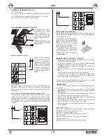
MONITOR INSTALLATION (FIG. 1-2, Page 11)
- The monitor should be installed far away from sources of light,
heat and electrical disturbances.
- Fix metal hooking plate to the wall with fixing screws supplied,
keeping top of panel at 1,40 m. from ground level.
- A drilling is forseen in order to fix the plate to a module flush-
mounted back box.
- Carry out connections on monitor terminal block following the dia-
grams.
- Hook the monitor following the arrow 1 and 2 direction .
- To remove the monitor from the hooking plate, operate with a
screwdriver on the security lock and remove it following the ar-
rows 1 and 2 in the opposite direction.
The monitor can be transformed into desk-top version by using the
proper conversion kit type 661A (Fig. 4, page 11).
CONNECTIONS
The two connecting wires between power supply and monitor can
be inverted.
- The advised section for the two conductors is of 0,75 mm²
(twi-
sted pair)
. The following features cannot be guaranted if the sec-
tion is different.
- The installation is guaranted for a good operation with 100 m ma-
ximum distance from the power supply to the monitor.
- In any case the maximum distance between the camera and the
monitor must not exceed 120 m.
- The electric lock connected to the installation must have a maxi-
mum of 1A power consumption with 12V voltage.
- Humming sounds or electrical discharges may affect the appliance
good operation.
Operating dwell time:
The monitor, camera, door lock and auxiliary services mut operate
according to the following intermittent cycles.
Monitor and camera activation cycle:
max. 90 seconds activated, 90 seconds deactivated
Door lock cycle:
max. 30 seconds activated, 150 seconds deactivated
Auxiliary service cycle:
max. 90 seconds activated, 90 seconds deactivated
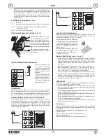
PROGRAMMING OF MONITOR TYPE 6358
2
3
5
4
1
When on the intallation
there is more than one mo-
nitor it is necessary to
identify the monitor with a
different code. The identifi-
cation code is assigned by
inserting the jumpers in
contacts 1 and 2 (ID0 and
ID1) as indicated in the fi-
gure.
ID 0
ID 1
1 2
ID1 ID0
MONITOR
n°1
n°2
n°3
n°4
Lock release
Removing contact 3 from the monitor it is possible to open the door
lock always, with monitor switched off or switched on. Inserting the
jumper, it is possible to release the door lock from the monitor only
after the call.
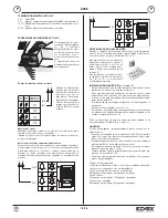
Association of call push-button from the entrance panel
To associate the entrance panel push-button with which to call and
switch on the monitor, operate on contacts 4 and 5: contact 4 for the
right hand panel push-button or 1° push-button and contact 5 for the
left hand push-button or 2° push-button. Inserting the jumpers the
call is excluded, removing them the call and the monitor activation is
enabled.
CH2
CH1
4 5
A B
C
VIDEO SIGNAL STABILISATION
If an image on the monitor is misshaped, displace jumper, placed on
the monitor fixing plate (R684, R682), to one of the following alterna-
tive positions “B” or “C”.
The operation of monitor is
managed by the 5 contact
setting on the back of mo-
nitor. To activate the fun-
ctions insert or remove the
jumpers supplied with mo-
nitor.
Programming must be car-
ried out before powering
the installation.
Monitor identification code
On installations where several moni-
tors are connected in series between
them, place only the jumper of last
monitor to the “B” or “C” position
and kepp the other jumpers of other
monitors in the “A” position.
On installations with more monitors
connected in star configuration,
place the jumper to the “B” or “C”
position only on the monitor with mi-
sshaped image.
CH2
CH1
4 5
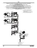
TERMINALS OF MONITOR TYPE 6358
1,2) BUS
Line
3,4)
For connection of additional chime type 860A (see variation
1)
12, 13) Additional power supply art. 6923 (terminal 12 = positive)
V3, M) connection for outdoor call push-button.
4/16
6358
GB


