background image

GB

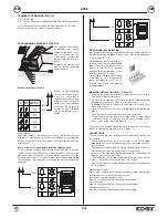
INSTALLAZIONE DEL MONITOR (fig. 1-2 pag 11)

-

Scegliere il luogo per installare il monitor, lontano da fonti luminose,
di calore e di disturbo elettrico.

-

Fissare alla parete la piastra di aggancio del monitor con i tasselli in
dotazione a metri 1,40 dal pavimento al bordo inferiore della piastra
stessa.

-

E' prevista la foratura per fissare la piastra ad una scatola da incasso
rettangolare a tre moduli.

-

Eseguire i collegamenti sulla morsettiera del monitor seguendo gli
schemi.

-

Inserire il monitor seguendo il senso delle frecce 1 e 2. 

-

Per togliere il monitor dalla piastra di aggancio, agire con un cac-
ciavite sulla linguetta di sicurezza ed estrarlo seguendo in senso in-
verso le frecce 1 e 2.

Si può trasformare il monitor in versione da tavolo utilizzando l'apposito
kit di trasformazione Art. 661A (fig. 4 pag. 11)

COLLEGAMENTI

I due fili di collegamento tra alimentatore e monitor possono essere
invertiti tra loro.

- La sezione consigliata dei 2 conduttori è di 0,75 mm² binato

(twistato)

. Se il cavo non presenta tali caratteristiche, non si

garantisce quanto descritto nel seguito.

- L'impianto è garantito per un buon funzionamento con una dis-

tanza massima tra alimentatore e monitor di 100 m.

- L'impianto è garantito per un buon funzionamento con una dis-

tanza massima tra alimentatore e telecamera di 100 m.

- Comunque la distanza complessiva tra monitor e telecamera non

deve essere superiore a 120 m.

- La serratura elettrica collegata all'impianto dovrà avere un assor-

bimento massimo di 1A alla tensione di 12V.

- Disturbi o scariche elettriche possono ripercuotersi sul buon 

funzionamento delle apparecchiature.

TEMPI DI FUNZIONAMENTO 

Il monitor, la telecamera, la serratura e servizi ausiliari devono fun-
zionare con i seguenti cicli di intermittenza.

Ciclo accensione monitor e telecamera:
90 secondi massimi acceso, 90 secondi spento 
Ciclo serratura:
30 secondi massimi attiva, 150 secondi disattiva
Ciclo servizi ausiliari
90 secondi massimi attivo, 90 secondi disattivo.

CH2

CH1

4 5

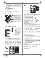
STABILIZZAZIONE SEGNALE VIDEO

Nel caso in cui l’immagine rappresentata nel videocitofono fosse di-
storta, spostare il ponticello posto sulla piastra di fissaggio (R684,
R682) del videocitofono, in una delle posizioni alternative “B” o “C”.

A B

C

Negli impianti dove sono presenti più
videocitofoni collegati in serie, spostare
il ponticello solo dell’ultimo videocito-
fono nella posizione “B” o “C” e mante-
nere gli altri ponticelli degli altri
videocitofoni nella posizione “A”.
Negli impianti con più videocitofoni col-
legati tra di loro a stella, spostare il pon-
ticello dei videocitofoni con l’immagine
distorta nella posizione “B” o “C”.

Video door entry unit with 3.5” colour flat screen 6358, are to be used
as a supplementary video door entry unit in 2-Wire video door entry
kits series 682x.

OPERATION

Carry out connections as described in this leaflet. When entrance
panel push-button is pressed, a call signal is heard on monitor (and
faintly also in the speech unit). The monitor comes on immediately
showing a clear image of the caller. Lift the handset to communicate
with the caller. If , on calling, the handset is already unkooked, the
audio connection is immediately established.  
If required operate the electric lock  by pressing proper push-button

. The monitor turns off after nearly 30'' (adjustable on the panel

from 30 to 90 seconds). The installation can be switched on by pres-

sing the push-button with the symbol 

, thus allowing an exter-

nal view when required.
When two cameras are installed, both cameras are cyclically activa-
ted on pressing the push-button.
The following item is designed for use with hearing aids used by hea-
ring impaired people. To activate it, select the “T” position on the
hearing aid.

TECHNICAL  CHARACTERISTICS OF MONITOR TYPE 6358

- Surface wall-mounted monitor  in ABS.
- Back plate and expansion plugs or 3 module back box for surface

wall-mounting.

- TFT LCD 3,5” screen for type 6358.
- Electronic circuit on interchangeable cards
- Standard video signal PAL (6358)
- Operating temperature: 0° to +40° C
- Electronic chime
- Input for outdoor call with ton different from the entrance panel call.
- Output for additional chime Art. 860A
- Supply voltage from the bus.
- Input for additional power supply (type 6923), if the installation is

configurated for the simultaneous switching on of two monitors.

- Configuration (through jumpers) to disable the chime from one o

more entrance panel push-buttons.

- Configuration (through jumpers) to block the lock activation when

the monitor is switched off. 

- External dimensions: 204x220x74

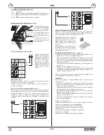
CONTROLS (Fig. 3, Page 11)

- Chime volume adjustment by means of cursor "A"
- Brightness control: through knob "B"
- Contrast control: through knob "C"

- Push-button for electric lock release 

- Autoswitching push-button 

- Push-button 

for 1st auxiliary service (allows activation of 1st

relais type 682R).

- Pressing push-buttons 

and  

at the same time, the 2nd

auxiliary service (allows activation of 2nd relais type 682R).

- LED for exlusion of  chime "D". It lights up with a steady light when

the chime has been excluded by using the "A" cursor and it fla-
shes when there is a conversation in progress on the installation
("engaged" signalling).

- LED for open door "E". When using only an entrance panel the

LED remains lit steadily when the door is open. When two doors
are installed, it remains lit steadily when both door locks are open.
On the contrary if only one of the doors is open, the LED flashes
once for the first door, twice for the second door. 

3/16

6358

I

Содержание 6358

Страница 1: ...OR FOR VIDEOKIT 2 WIRES MONITEUR POUR KIT VIDÉO 2 FILS NEW MODEL YEAR 2011 220 mm 74 mm 204 mm Il prodotto è conforme alla direttiva europea 2004 108 CE 2006 95 CE e successive Product is according to EC Directive 2004 108 CE 2006 95 CE and following norms Le produit est conforme à la directive européenne 2004 108 CE 2006 95 CE et suivantes Das Produkt entspricht den europäischen Richtlinien 2004 ...

Страница 2: ...e A Controllo luminosità attraverso la manopola B Controllo contrasto attraverso la manopola C Pulsante comando serratura Pulsante autoaccensione impianto Pulsante per 1 servizio ausiliario permette l attivazione del primo relè dell Art 682R Premendo assieme i pulsanti ed si attiva il 2 servizio ausiliario l attivazione del secondo relè dell Art 682R LED suoneria esclusa D Si accende di luce fissa...

Страница 3: ...Video door entry unit with 3 5 colour flat screen 6358 are to be used as a supplementary video door entry unit in 2 Wire video door entry kits series 682x OPERATION Carry out connections as described in this leaflet When entrance panel push button is pressed a call signal is heard on monitor and faintly also in the speech unit The monitor comes on immediately showing a clear image of the caller Li...

Страница 4: ...on the intallation there is more than one mo nitor it is necessary to identify the monitor with a different code The identifi cation code is assigned by inserting the jumpers in contacts 1 and 2 ID0 and ID1 as indicated in the fi gure ID 0 ID 1 1 2 ID1 ID0 MONITOR n 1 n 2 n 3 n 4 Lock release Removing contact 3 from the monitor it is possible to open the door lock always with monitor switched off ...

Страница 5: ...rie A Réglage de la luminosité à travers de la poignée B Règlage du contrast à travers de la poignée C Poussoir commande gâche Poussoir autoallumage installation Poussoir pour 1er service auxiliare il permet l activation du relais Art 682R En appuyant simultanément sur les poussoirs et on active le 2ème service auxiliare et l activation du relais Art 682R LED sonnerie exclue D Lorsque la sonnerie ...

Страница 6: ... abheben Wenn beim Ruf der Hörer schon abgehoben ist wird die Sprechverbindung sofort dur chgeführt Eventuell den Türöffner durch Drücken der entsprechen den Taste betätigen Nach Ablauf von 30 Sekunden regelbar am Klingeltableau von 30 bis max 90 Sekunden schaltet sich der Mo nitor aus Die Anlage kann auch jederzeit von innen durch Drücken der Taste mit dem Symbol am Monitor eingeschaltet werden S...

Страница 7: ...ren Die Programmierung muss vor der Versorgung der Anlage durchge führt werden IDENTIFIZIERUNGSCODE DES MONITORS Bei Anlagen mit mehreren Monitoren in Serienschaltung nur die Brücke des letzten Monitors auf B oder C setzen und die Brücken der anderen Monitore in Stellung B oder C stecken lassen Bei Anlagen mit mehreren Monitoren in Sternschaltung nur beim Monitor mit verzerrtem Bild die Brücke in ...

Страница 8: ...ol contraste por medio de la manopla C Pulsador mando cerradura Pulsador autoencendido instalación Pulsador para 1er servicio auxiliar permite la activación del relé Art 682R Presionando simultáneamente los dos pulsadores ed se activa el 2do servicio auxiliar permite la activación del relé Art 682R LED timbre excluído D Se enciende con luz fija cuando el tim bre viene excluído por medio del cursor...

Страница 9: ... DE FUNCIONAMENTO Efectuar a instalação conforme as instruções unidas Premindo um botão da botoneira ouvir se á no monitor um sinal acú stico e débilmente mesmo no posto externo O monitor ilumina se imediatmente mostrando claramente o sujeito presente diante a te lecâmara Para conversar com o exterior levantar o punho Se for necessário activar o trinco eléctrico premindo o botão adequado Decorrido...

Страница 10: ...o PROGRAMAÇÃO DO MONITOR ART 6358 2 3 5 4 1 Quando na instalação há mais do que um monitor é necessário identificar os monitores com um có digo diverso O código de identificação é assinalado através da inserção das pontes nos contactos 1 e 2 ID0 e ID1 como indica a figura ID 0 ID 1 1 2 ID1 ID0 MONITOR n 1 n 2 n 3 n 4 Abertura do trinco Retirando a ponte do contacto 3 do monitor é possível abrir o ...

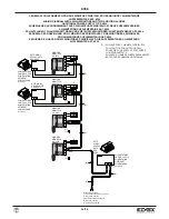
Страница 11: ...WITH MINIMUM SECTION OF 0 75 FOR A MAXIMUM OF 100 METRES DEUX FILS AVEC SECTION MINIMALE DE 0 75 POUR UN MAXIMUM DE 100 MÈTRES ZWEI DRÄHTE MIT MIN QUERSCHNITT VON 0 75 MM BIS MAX 100 M DOS HILOS DE SECCIÓN MÍNIMA 0 75 PARA UN MÁXIMO DE 100 METROS DOIS FIOS DE SECÇÃO MÍNIMA 0 75 PARA UM MÁXIMO DE 100 METROS VIDEOKIT ART 68 RC E 68 RC2 A COLORI VIDEOKIT TYPE 68 RC AND 68 RC2 COLOUR VIDEOKIT ART 68 R...

Страница 12: ... CHIAMATA FUORIPORTA PUSH BUTTON FOR OUTDOOR CALL POUSSOIR POUR APPEL PORTE PALIÈRE WOHNTÜRRUFTASTE PULSADOR LLAMADA PUERTA PARTAMIENTO BOTÃO PARA CHAMADA NO PATAMAR N si171 MONITOR MONITEUR Art 6358 ALIMENTATORE POWER SUPPLY ALIMENTATION NETGERÄT ALIMENTADOR Art 692K RETE MAINS RÉSEAU NETZ RED REDE Alla targa esterna To the external entrance panel À la plaque externe Zum Externklingeltableau A la...

Страница 13: ...NTATORE POWER SUPPLY ALIMENTATION NETGERÄT ALIMENTADOR Art 692K N si172 RETE MAINS RÉSEAU NETZ RED REDE D PULSANTE PER CHIAMATA FUORIPORTA PUSH BUTTON FOR OUTDOOR CALL POUSSOIR POUR APPEL PORTE PALIÈRE WOHNTÜRRUFTASTE PULSADOR LLAMADA PUERTA PARTAMIENTO BOTÃO PARA CHAMADA NO PATAMAR CITOFONO PHONE POSTE HAUSTELEFON TELEFONO TELEFONE Art 62I8 6208 Alla targa esterna To the external entrance panel À...

Страница 14: ...ADOR SUPLEMENTARIO ART 6923 ESQUEMA DE LIGAÇÃO COM 2 MONITORES PRINCIPAIS Y DOIS SUPLEMENTARES ALIMENTADOR SUPLEMENTAR ART 6923 ALIMENTATORE POWER SUPPLY ALIMENTATION NETGERÄT ALIMENTADOR Art 692K ALIMENTATORE POWER SUPPLY ALIMENTATION NETGERÄT ALIMENTADOR Art 6923 ALIMENTATORE POWER SUPPLY ALIMENTATION NETGERÄT ALIMENTADOR Art 6923 RETE MAINS RÉSEAU NETZ RED REDE D PULSANTE PER CHIAMATA FUORIPORT...

Страница 15: ...nto modulo relè Art 170A 101 per comando di suonerie supplementari a timpano Wiring diagram for relay Art 170A 101 for additional bell Schéma de raccordement relais Art 170A 101 pour sonneries supplémentaires Schaltplan des Relais Art 170A 101 für zusätzliche Klingeln Esquema de conexionado relé Art 170A 101 para timbres suplementarios Esquema de ligação relé Art 170A 101 para campaínhas suplement...

Страница 16: ...pt 39 049 9202601 elvoxexp elvox com www elvox com FILIALI ESTERE FILIALI ITALIA Torino Strada del Drosso 33 8 10135 Torino Milano Via Conti Biglia 2 20162 Milano ELVOX Austria GmbH Grabenweg 67 A 6020 Innsbruck CERT n 9110 ELVO UNI EN ISO 9001 2008 ELVOX Shanghai Electronics Co LTD Room 2616 No 325 Tianyaoqiao Road Xuhui District 200030 Shanghai Cina ...

Отзывы: