background image

14 

www.eltherm.com

14 

Operating instructions 

Ex – Temperature Controller Ex-TC/…-It

BU 122-It

Revision 2

• 

Conduct a visual inspection at suitable intervals to ensure 
the Ex-TC is undamaged and securely seated in consider-
ation of the installation location and application.

• 

Retighten the cable entries if necessary. Damaged parts 
must be replaced by qualified personnel

• 

Protect the Ex-TC devices against damage in the event of 

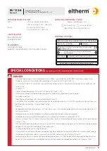
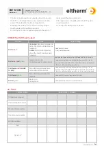
OPERATING STATES (all models)

LED state

Cause

Contact setting

Flashes 

red


Controller: 

Recorded temperature 

below the limit for undertempera-
ture alarm 

Limiter: 

Recorded temperature 

above the limit for overtempera-
ture alarm

Load contact closed
Alarm contact opened

Flashes 

red

 and 

green

Setpoint set to 000,
Controller expects setpoint entry

load contact opened, alarm contact opened; for  /AL model:  
Load contact opened and locked (can be manually reset by 
pressing the reset button after eliminating the sensor problem; 
status saved for possible power failure)

Continuous 

red

 (model /

AL only)

Recorded temperature above 
set maximum temperature

Load contact opened and locked (can be manually reset by 
pressing the reset button after safe temperatures are restored; 
status saved for possible power failure), alarm contact opened

Continuous 

green

Recorded temperature below 
setpoint

Load contact closed, alarm contact closed

Flashes 

green

Device is in 
setting mode

Load contact opened, alarm contact closed

SETTINGS

COMMISSIONING

MAINTENANCE / CHANGE

Temperature setpoint

Undertemperature alarm

Maximum temperature

Overtemperature alarm

MODBUS address

Date

Signature

repair work to heated system parts.

• 

After repair work is complete, check the EX-TC again 
(visual inspection).

• 

Do not operate damaged Ex-TC devices.

Содержание Ex-TC It Series

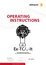
Страница 1: ... Ernst Heinkel Straße 6 10 57299 Burbach Germany T 49 2736 4413 0 F 49 2736 4413 0 info eltherm com BU 122 It www eltherm com Ex TC It Assembly and Operation Ex TC A It Ex TC AL It Ex TC M It OPERATING INSTRUCTIONS ...

Страница 2: ...nfo eltherm com Document BU 122 It Installation and Operation of Ex TC It Autor Peter Schmidt Revision 2 10 02 2022_dm 30 10 2019 Reservation We reserve the right to make technical changes Changes errors and misprints do not justify any no claim for compensation For safety com ponents and systems the installation instructions and the relevant standards and regulations must be observed ...

Страница 3: ...TES SETTINGS 4 4 4 4 5 6 6 6 6 6 7 7 7 7 8 10 11 11 12 13 13 14 14 Particularly important points in these instructions are marked by symbols important information and instructions for safe effective and environmentally compatible use NOTE i indicates an potential dangerous situation If it is not avoided there is a risk of damage or malefunction CAUTION WARNING indicates a dangerous situation If it...

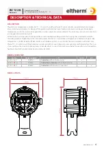
Страница 4: ...flanged onto the housing that is optimally suited for mounting pipelines Depending on the intended purpose the Ex TC is available as a temperature controller with alarm relay temperature controller including RS 485 interface with Modbus protocol or a controller limiter combination with alarm relay The Ex TC It is able to switch high nominal currents and with its round shape it ensures optimum mech...

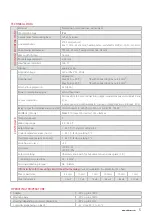
Страница 5: ...d 3 or 3 wire connection with automatic conductor compensation up to max 20 Ω Relay output for collective alarm not M 1 N O contact 3 A 250 VAC 100 VA or 5 A 24 VDC 100 W MODBUS M only RS485 RTU max 120 devices Um 6Vmax Temperature unit C Measuring range 99 450 C Setpoint range 1 450 C T1 factory setting 5 C Undertemperature alarm not L 1 450 C factory setting 0 C Overtemperature alarm AL only 1 4...

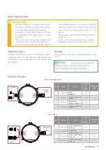
Страница 6: ...ing ring O ring or shaped sealing elements For operation at ambient temperatures 40 C or with currents 20A the connection cables with cross sections of at least 2 5 mm must be used The cable entries must be checked to ensure they are suitable for the connecting line provided In addition to an overcurrent protective device a FI circuit breaker in conformity with EN 60079 30 1 must be installed in T...

Страница 7: ...e data on the type plate with the data on the delivery slip to make certain the correct materials have been delivered STORAGE Store in a dry environment at an ambient temperature of 0 C to 50 C the applicable regulations This manual is intended for that group of persons and contains all important infor mation required for working safely with Ex TC control devices The manual must be retained with t...

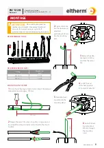
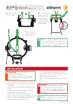
Страница 8: ... 23 24 M25x1 5 24 29 1 Do not fasten heating cable and sensor line at the planned measurement point approx 500 mm 2 Prepare the end of the sensor line with a strong wire and by using adhesive tape to lead a sensor line into the mount ing base 4 Cut off the end of the heating cable at an angle of about 45 2 Lead a sensor line into the opening pro vided and pull it about 200 mm into the mounting bas...

Страница 9: ... the locking arm for ward a few millimetres by turning the screwdriver 3 Turn the headless screw back with the Allen wrench size 2 until it is protruding slightly out of the locking arm OPENING THE HOUSING 1 Tighten the headless screw with an Allen wrench size 2 until the locking arm is flush with the side bars 4 Raise the cover using the screwdriver 5 Open the cover using the screwdriver REMOVING...

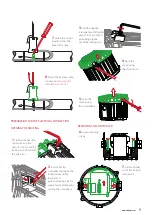
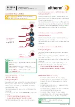
Страница 10: ...ell as any seals and O rings in or on it to make certain they are clean and not damaged All the cables that are inserted must be laid permanently in place Connecting threads can be fitted with suitable reduc tions Reductions must not be nested Follow the order of assembly without exception Guide a cable of the correct type and fitted appropriately into the housing Do not tighten the cable glands y...

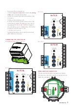
Страница 11: ...well as the heating cables to the corresponding terminals Tighten the terminals finger tight torque between 0 6 and 0 8 Nm Tighten unused terminals as well Push the controller back into the lower position of the slotted holes and tighten the retaining screws see fol lowing page INSTALLING THE CONTROLLER page 11 Close all openings covers threaded holes cable entries Take into account the torques in...

Страница 12: ...ue rotary knobs of the controller The selected value can be seen in a recess at the edge of the rotary knob To confirm press the reset button until the LED goes out Then the desired temperature setpoint must be set again After 100 seconds the setting menu closes automatically without any values being saved Setting the temperature setpoint Ex TC It A AL and M Setting the maximum temperature Ex TC I...

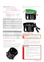
Страница 13: ... cover to ensure they are not damaged Cover can only be inserted in one position locking arms twist protection recesses have different width Move the cover to the appropriate position 2 Attach the cover with the narrower locking arm without a headless screw close the cover and 3 Use the pliers to lock the cover OPERATION MAINTENANCE Observe the locally applicable safety regulations when the Ex TC ...

Страница 14: ...ntry load contact opened alarm contact opened for AL model Load contact opened and locked can be manually reset by pressing the reset button after eliminating the sensor problem status saved for possible power failure Continuous red model AL only Recorded temperature above set maximum temperature Load contact opened and locked can be manually reset by pressing the reset button after safe temperatu...

Страница 15: ...15 www eltherm com 15 www eltherm com NOTES ...

Страница 16: ...ructions Ex Temperature Controller Ex TC It EN DISPOSAL The WEEE logo indicates that this product must not be disposed of with residential waste Further information about disposal and recycling of old electrical and electronic devices and where to find collection points is available from your local disposal company or from the manufacturer from which you bought the product NOTE i ...

Отзывы: