Section 2. Installation
7
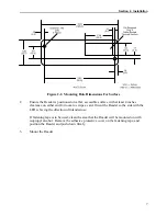
Figure 2-2. Mounting Hole Dimensions For Surface
2.
Ensure the Reader is positioned on a flat, accessible surface with at least 4 inches
clearance on either end for room to swipe a card. Orient the Reader so the side with the
LED is facing the direction of intended use.
If fastening tape is to be used, clean the area that the Reader will be mounted on with
isopropyl alcohol. Remove the adhesive protective cover on the fastening tape, and
position the Reader and push down firmly.
3.
Mount the Reader.
Содержание ET1725L Series
Страница 1: ......
Страница 26: ...3 22 E l o E n t u i t i v e T o u c h m o n i t o r U s e r G u i d e...
Страница 37: ...C 33 17 LCD Touchmonitor Dimensions 478 434 429 370 338 270 3 43 219...
Страница 41: ...37 N10051...
Страница 42: ...38 E l o E n t u i t i v e T o u c h m o n i t o r U s e r G u i d e...
Страница 52: ...vi Figure 1 1 Port Powered Swipe Reader...
Страница 56: ...Port Powered Swipe Reader 4 Figure 1 3 Dimensions...
Страница 60: ...Port Powered Swipe Reader 8...
Страница 69: ...vi Figure 1 1 USB Swipe Reader...
Страница 73: ...USB Swipe Reader 4...
Страница 77: ...USB Swipe Reader 8...
Страница 79: ...USB Swipe Reader 10...
Страница 99: ...viii Figure 1 1 MagTek Devices and Device Drivers for Windows MTD MagTek Device Drivers for Windows...
Страница 127: ...MagTek Device Drivers for Windows 28...
Страница 137: ...MagTek Device Drivers for Windows 38...
Страница 151: ...MagTek Device Drivers for Windows 52...
Страница 173: ...MagTek Device Drivers for Windows 74...
Страница 175: ...MagTek Device Drivers for Windows 76...
Страница 177: ...MagTek Device Drivers for Windows 78...
Страница 192: ......


