5
SECTION 2. INSTALLATION
This section describes the cable connection, the Windows Plug and Play Setup, and the physical
mounting of the unit.
USB CONNECTION
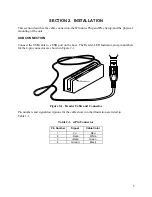
Connect the USB cable to a USB port on the host. The Reader, LED Indicator, and pin numbers
for the 4-pin connector are shown in Figure 2-1.
LED Indicator
1
4
Figure 2-1. Reader Cable and Connector
Pin numbers and signal descriptions for the cable shown in the illustration are listed in
Table 1-1.
Table 2-1. 4-Pin Connector
Pin Number
Signal
Cable Color
1 V
CC
Red
2 -
Data
White
3 +Data
Green
4 Ground
Black
Содержание ET1725L Series
Страница 1: ......
Страница 26: ...3 22 E l o E n t u i t i v e T o u c h m o n i t o r U s e r G u i d e...
Страница 37: ...C 33 17 LCD Touchmonitor Dimensions 478 434 429 370 338 270 3 43 219...
Страница 41: ...37 N10051...
Страница 42: ...38 E l o E n t u i t i v e T o u c h m o n i t o r U s e r G u i d e...
Страница 52: ...vi Figure 1 1 Port Powered Swipe Reader...
Страница 56: ...Port Powered Swipe Reader 4 Figure 1 3 Dimensions...
Страница 60: ...Port Powered Swipe Reader 8...
Страница 69: ...vi Figure 1 1 USB Swipe Reader...
Страница 73: ...USB Swipe Reader 4...
Страница 77: ...USB Swipe Reader 8...
Страница 79: ...USB Swipe Reader 10...
Страница 99: ...viii Figure 1 1 MagTek Devices and Device Drivers for Windows MTD MagTek Device Drivers for Windows...
Страница 127: ...MagTek Device Drivers for Windows 28...
Страница 137: ...MagTek Device Drivers for Windows 38...
Страница 151: ...MagTek Device Drivers for Windows 52...
Страница 173: ...MagTek Device Drivers for Windows 74...
Страница 175: ...MagTek Device Drivers for Windows 76...
Страница 177: ...MagTek Device Drivers for Windows 78...
Страница 192: ......


