background image

Manual Ip to ESPA 444 converter

Page 4

Date: 7 may 2013

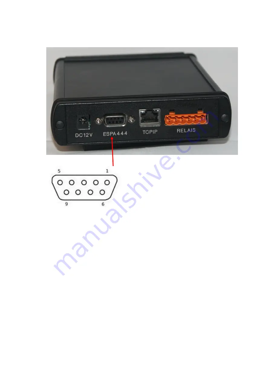
Connect to the ESPA44 equipment:

The convertor uses a standard 9p SUBD connector to connect to the ES-
PA444 equipment.

The pinlayout is:

Pin 2:

TxD

Pin 3:

RxD

Pin 5:

GND

Pin 7:

CTS

Pin 8:

RTS

We stronly recommend to secure the RS232 cable to the housing using the
screw mounts.

More settings, like baudrate and more, are beïng setup via TCP/IP or the
RS232 diagnoseport. For further information see the associated document.

For status information about the communication via ESPA4.4.4.  see page 7
of this document.

Содержание IP to Espa 444

Страница 1: ...Manual Ip to ESPA 444 converter Page 1 Date 7 may 2013 Setup the IP to Espa 444 Convertor Ip to Espa 444 Convertor www elexol nl ...

Страница 2: ...rter Page 2 Date 7 may 2013 Connect to the TCP IP network 3 Connect to the ESPA444 equipment 4 Connect the power 5 Connect the output relays 6 Opening the cab for the status leds 7 The status leds 8 Using the diagnoseport 9 Index ...

Страница 3: ...e is connected to the RJ45 socket As soon as the connection is made and the device is powered up the green led lights up to indicate the networkconnction More status information on the TCP IP port can be found behind the cab on the other side of the housing See Page 7 of this document for further explanation ...

Страница 4: ...pinlayout is Pin 2 TxD Pin 3 RxD Pin 5 GND Pin 7 CTS Pin 8 RTS We stronly recommend to secure the RS232 cable to the housing using the screw mounts More settings like baudrate and more are beïng setup via TCP IP or the RS232 diagnoseport For further information see the associated document For status information about the communication via ESPA4 4 4 see page 7 of this document ...

Страница 5: ...Manual Ip to ESPA 444 converter Page 5 Date 7 may 2013 Connect the power to the converter The power supply of the Converter is 12V DC It is advised to use the power supply shipped with the con verter ...

Страница 6: ... Ip to ESPA 444 converter Page 6 Date 7 may 2013 Connect the ouput relays 1 Relay 1 Common 2 Relay 1 Normally Open 3 Relay 1 Normally Closed 4 Relay 2 Common 5 Relay 2 Normally Open 6 Relay 2 Normally Closed ...

Страница 7: ...r Page 7 Date 7 may 2013 Opening the cover to see the status leds and access the diagnoseport To open the cover press it to the upward position marked 1 and open it by using a screwdriver on the top side of the cover marked 2 1 1 2 ...

Страница 8: ...buffer Flashes short red each second An error is just detected Flashes short red continuous An error remains to long Flashes orange New settings are programmed After a few seconds these new settings are loaded into the converter and the orange flashing stops Link Flashes short each second The converter is waiting for a connection on TCP IP side Lits up continuous The converter is connected via TCP...

Страница 9: ...iagnoseport is used to set up the Converter If needed the Converter can be set up using the ConfigTool IP It is also possible to get diagnostic information out of the converter in case of problems Connect the 9 pole subd to the laptop with a straight forward 1 on 1 9 pole cable ...

Отзывы: