Shenzhen Elephant Robotics Technology Co., Ltd.
28
4
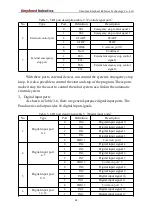
24V
DC 24V
5
OUT10
Digital output signal
10
6
24V
DC 24V
7
OUT11
Digital output signal
11
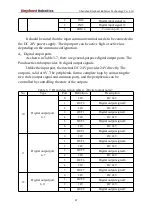
13
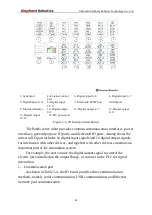
Digital output port
12~15
0
24V
DC 24V
1
OUT12
Digital output signal
12
2
24V
DC 24V
3
OUT13
Digital output signal
13
4
24V
DC 24V
5
OUT14
Digital output signal
14
6
24V
DC 24V
7
OUT15
Digital output signal
15
5
,
DC power port
As shown in Table 3-8, the IO board provides an internal DC 24V for the
user to use.
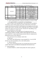
Table 3- 8 IO port description table 5
(
DC power port
)
No.
Type
Port
Definition
Description
14
DC power port
0
24V
Internal DC power supply 24V
1
24V
2
24V
3
24V
4
GND
Internal DC power supply GND
5
GND
6
GND
7
GND
3.7.2 IO port principle and application
1
,
Digital input port
As shown in Figure 3-7, the input signal is driven through the current-
limiting resistor R to allow the internal circuit to detect it. The difference
between the PNP input and the NPN input is that one end of the PNP input is
connected to 0V, and one end of the NPN input is connected to 24V.

