background image

Shenzhen Elephant Robotics Technology Co., Ltd.

4

WARNING: Conditions that may cause a hazard that, if not avoided,

could result in personal injury or serious damage to the equipment.

Be careful of electric shock: It may cause dangerous use of electricity. If it

is not avoided, it may cause personal injury or serious damage to

equipment.

Prohibited: Things that are not allowed to do.

Caution: Important things to be noted.

1.3 Hazard identification

The safety of the collaborative robot is based on the premise of proper

configuration and use of the robot, and even if all safety instructions are

observed, the injury or damage caused by the operator may still occur.

Therefore, it is very important to understand the safety hazards of robot use,

which is beneficial to prevent problems before they occur.

Tables 1-2~4 below are common safety hazards that may exist in the

context of using robots:

Table1- 2 Dangerous safety hazards

1 Personal injury or robot damage caused by incorrect operation during robot handling.

2

Personal injury or robot damage caused because the robot is not fixed as required, for

example, the screw is not screwed or tightened, and the base is not enough to stably

support the robot for high-speed movement, causing the robot to tip down.

3 Failure to perform proper safety function configuration of the robot, or installation of

safety protection tools, etc., may cause the safety function of the robot to fail.

Содержание Panda 3

Страница 1: ...ant Robotics Technology Co Ltd Elephant Robotics User Manual Panda Series Robot Version 1 0 Language English Compiled in 2019 01 Copyright 2017 2019 Shenzhen Elephant Robotics Technology Co Ltd All ri...

Страница 2: ...ssion of Shenzhen Elephant Robotics Technology Co Ltd hereinafter referred to as Elephant Robotics In addition the product information and related resources mentioned in this manual are for reference...

Страница 3: ...t 11 2 1 Overview to the robot system 11 2 2 Robot 12 2 2 1 Characteristics of the robot 12 2 2 2 Model 12 2 2 3 Robot joint introduction 13 2 3 Scope of work 14 2 4 Active load 14 2 5 Technical Param...

Страница 4: ...ned in Elephant Robotics and have the mechanical and electronic knowledge required for the above work How to use This manual should be used when doing the following works Installation work Move the ro...

Страница 5: ...will only repair the failures that occur when the robot is normally used However in the following cases the customer will be charged for repairs even during the warranty period 1 Damage or malfunction...

Страница 6: ...ent should be performed to maximize personal safety and property safety This chapter provides a basic guide to safe use by introducing different safety alert symbols and precautions 2 Interpretation o...

Страница 7: ...r damage caused by the operator may still occur Therefore it is very important to understand the safety hazards of robot use which is beneficial to prevent problems before they occur Tables 1 2 4 belo...

Страница 8: ...should you stand under any axis of the robot 7 The robot is a precision machine If it is not placed smoothly during handling it may cause vibration and may cause damage to the internal components of t...

Страница 9: ...nd warning symbols on the equipment and ensure that all warning signs and warning symbols are complete and clear and that all safety devices are secured before opening and starting the equipment And m...

Страница 10: ...ncy stop state is canceled and before the servo power is turned on it is necessary to remove the obstacles and faults that cause the emergency stop and then turn on the servo power 19 Please pay atten...

Страница 11: ...ronment that may cause an explosion Used directly without risk assessment Insufficient use of safety function levels Inconsistent use of robot performance parameters 1 7 Emergency stop This section de...

Страница 12: ...er equipment at the same time you can use the external E STOP double loop circuit user need to short it when not in use 1 7 2 Collision checking During the operation of the robot it is possible to tou...

Страница 13: ...Ltd 10 If the software pops up with a fatal error message please activate the emergency stop quickly write down the condition that caused the error and contact your supplier In the event of a fire us...

Страница 14: ...s the number of cable cores connected from the body to the controller and also improves the stability and anti interference ability of the cable transmission data and reduces the cost The main materia...

Страница 15: ...e and transformation of independent stations compared to the traditional robotic deployment of the entire automated production line The customer or system integrator can choose the adapted end effecto...

Страница 16: ...the robot body is shown in Figure 2 2 The mechanical body of the Panda series robot can be thought of as an open chain multi link mechanism The start link is the base of the robot the end link is conn...

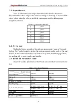
Страница 17: ...e under loads of 3kg and below The Panda 5 robot is rated at 5kg and can operate under loads of 5kg and below As the load moves further and further away from the J6 flange position its payload will be...

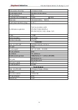
Страница 18: ...3848 2008 PL d EN ISO 10218 1 2011 Clause 5 4 3 Noise 70dB Robot mounting Any angle Relative humidity 5 95 Controller Size L W H 545mm 285mm 433mm Weight 25kg Power supply AC 110 240V 50 60Hz IP class...

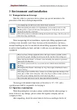
Страница 19: ...ease use heavy lifting equipment such as driving as much as possible and be careful of the people standing around to prevent the machine from rolling over When carrying the Panda 3 or Panda 5 robot ma...

Страница 20: ...allation 3 4 1 Installation requirements The actual weight of the Panda 3 robot is 17kg The actual weight of the Panda 5 robot is 24 5kg Considering the movement of the robot the center of gravity wil...

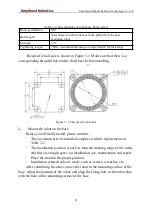
Страница 21: ...e 3 1 The specific hole size 2 Mount the robot on the base Before you officially install please confirm The environment to be installed complies with the requirements of Table 3 1 The installation pos...

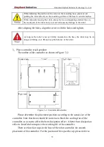
Страница 22: ...on the base the robot may be in danger of falling over Please keep the balance of the robot 3 Place controller teach pendant The outline of the controller as shown in Figure 3 2 Figure 3 2 Controller...

Страница 23: ...from the robot body beyond the length of the connecting cable Choose the placement position of the controller try to avoid possible problems such as the controller being bumped or close to the wall no...

Страница 24: ...The specific information is shown in Table 3 3 Table 3 3 Main cables of the robot Type Connection Length Use description Controller power cord External power supply controller 2m Power supply to the e...

Страница 25: ...peration Before wiring turn off the power of the controller and related devices and pull up the warning sign eg do not turn on the power Wiring under power on conditions is extremely dangerous and may...

Страница 26: ...ant Robotics Technology Co Ltd 23 Figure 3 5 Robot system boot flow chart 3 7 IO Board 3 7 1 IO board introduction Figure 3 6 shows the IO board port of the Panda series robot Port details are shown i...

Страница 27: ...faces power interfaces general purpose IO ports and dedicated IO ports Among them the universal IO port includes 16 digital input signals and 16 digital output signals for interaction with other devic...

Страница 28: ...ial port can receive data while using one line to send data while using another line RS485 is half duplex and only one point can be sent at any time Therefore the transmitting circuit must be controll...

Страница 29: ...ink in the automatic control system 3 Digital input ports As shown in Table 3 6 there are general purpose digital input ports The Panda series robot provides 16 digital input signals Table 3 6 IO port...

Страница 30: ...form a complete loop by connecting the two ends output signal and common port and the peripherals can be controlled by controlling the state of the outputs Table 3 7 IO port description table 4 Digita...

Страница 31: ...ovides an internal DC 24V for the user to use Table 3 8 IO port description table 5 DC power port No Type Port Definition Description 14 DC power port 0 24V Internal DC power supply 24V 1 24V 2 24V 3...

Страница 32: ...rnal device inputs 0V the input signal is in the High state otherwise it is in the Low state vice versa Figure 3 8 Input application example diagram 2 Digital output port As shown in Figure 3 9 the ou...

Страница 33: ...Shenzhen Elephant Robotics Technology Co Ltd 30 Figure 3 9 Digital output port schematic Figure 3 10 shows an example of an output connection application Figure 3 10 Output application example diagram...

Страница 34: ...ts position Therefore in order to obtain the highest possible absolute positioning accuracy the robot must be calibrated the operation where the two origin positions are the same is called calibration...

Страница 35: ...a new system which means that all safety audit processes such as risk assessment must be updated Do not remove any parts unless otherwise stated in this manual The maintenance steps shall be strictly...

Страница 36: ...enance schedule No Contents Equipment Routine 1 month 3 months 6 months 12 months 1 Inspection Robot appearance 2 Cable interface 3 Motor reducer 4 Cable harnes s external 5 internal 6 Screw surface 7...

Страница 37: ...determine what components are abnormal Matters on repair inspection adjustment etc of the robot must be carried out by an authorized system integrator or agent Please contact a professional for dispos...

Отзывы: