Elektror SD 20 M Скачать руководство пользователя страница 12

12

Operating and assembly instructions SD

www.elektror.com

9016312 01.20/09

EN

•  Do not leave the side channel blower unprotected in the

  open (protect against ingress of moisture).
• Attach hoist securely. Only use hoists and load suspension

  devices with su

  cient load-carrying capacity. Secure the 

  route of transportation.

Note!

The eye bolt on the motor must not be used to 

lift the entire blower. This is unsed if the motor 

needs to be (dis-)assembled.

2.2 Storage

•  Ensure that the air intake connection and pressure 

  connection are closed. 
•  Store the side channel blower
  -> in its original packaging if possible

  -> in a closed room 

  -> in a dry, dust-free and vibration-free area.
•  Storage temperature range from -20°C to +60°C
•  After a storage period of 6 months, the bearings should 

  be checked before they are mounted in the side channel 

 blower.
•  Devices may be stored for a maximum of 2 years.

3 INFORMATION ON COMMISSIONING 
THE MACHINE

3.1 Basic information

• Prior to the 

fi

 rst start-up and before any other start-up, the 

proper operating status of the unit must be inspected. Units 

that, for example, are found to be defective upon delivery 

or during installation, must be examined by quali

fi

 ed techni-

cians.
• Installation, assembly and operation must only be performed 

by properly trained and quali

fi

 ed specialists. Operation fol-

lowing incorrect installation, maintenance or unapproved 

replacement of components constitutes non-designated use 

and renders the warranty void. The resultant risk shall be 

borne solely by the customer or owner.

3.2 Installation and assembly

•  Protect the side channel blower from the weather and 

  install it in a horizontal position - see also 1.1. For outdoor 

  use, protection from the weather must generally be pro-

  vided that ful

fi

 ls the requirements listed in 1.1 Intended 

  Use and protects the side channel blower from the in

fl

 u-

  ences of the weather.
•  Do not expose to vibrations or shocks. Permissible 

  vibrational load on side channel blower: refer to ISO  

 14694, BV-3.
•  Standard side channel blowers with base: Bolt securely  

  to a level and 

fi

 rm surface at the place of use, making 

  sure that the surface has adequate load-bearing capacity 

  and avoiding vibration transmission or vibrational load.
•  Side channel blowers placed on the rubber elements 

  provided must be secured against turning.

•  Blowers with motor (drive), belt drive and belt guard: The 

  buyer (plant manufacturer, operating company or other 

  customer) is solely responsible for safe, stable installation 

  and fastening in conjunction with the motor, belt drive and 

  belt guard to be provided by the customer, and for compli-

  ance with applicable standards and speci

fi

 cations.

•  Blower feet and consoles must be designed only for the 

  respective blower’s own weight.
•  Cover open intakes or outlets with protective grating 

  according to DIN EN ISO 13857.
•  The belt drive and rotating parts must be covered with a 

  belt guard according to DIN EN ISO 13857.
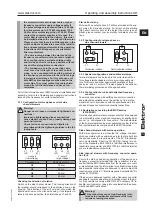
•  Ensure that the motor has adequate ventilation. 

  Permitted ambient temperatures with:

  Elektror motor and a rated voltage of 50 Hz or 60 Hz,

  Special voltages, multi-voltage motors, FU-compatible 

  versions, FUK versions, UL-certi

fi

 ed devices:

  • Ambient temperature -20°C to +40°C

Note!

Standard equipment as per IEC 60038 Elektror 

motors are generally designed for an extended 

voltage range of ±10%.

•  The performance of the drive motor’s ventilation system 

  must not be impaired by the installation situation.

3.3 Electrical connection

Note!

The work described in this section may only be 

performed by a quali

fi

 ed electrician. Connect the 

appliance to the power supply in the terminal box 

as per the wiring diagram and in compliance with 

the applicable local regulations.

Three-phase or a.c. motors can be used as drive motors. 

In the appliance designation, the letter D stands for three-

phase a.c. and the letter E for single-phase a.c.
•  The drive motor must be protected using a motor overload 

  switch (this does not apply to frequency converter oper-

  ated appliances). Where appliances are frequency-

  converter-operated, the existing temperature sensor 

  (PTC resistor sensor) or temperature switch (normally 

  closed contact) must be connected to the converter and 

 evaluated.
•  Check that the mains voltage matches the ratings on 

 the nameplate.
•  The safety earth terminal can be found in the terminal box.

Note!

For operation of the drive motor with a frequency 

converter, the following points should also be 

noted:
• Motors may only be operated on a frequency 

converter if they have “/FU” (which denotes 

“frequency converter compatible”) marked on 

the nameplate, or if they have been ordered as 

“frequency converter compatible” motors and 

con

fi

 rmed.

• The frequency converter supply voltage must 

only be a maximum of 400 V without the motor 

fi

 lter.  Appropriate measures, such as a motor 

fi

 lter to protect the motor, must be installed on 

Содержание SD 20 M

Страница 1: ...ktror Side Channel Blower Operating and Assembly Instructions EN Elektror Seiten kanalverdichter Betriebs und Montageanleitung DE SD 20 M SE 20 SD 22 M SE 22 SD 24 M SE 24 SD 2n M SE 2n SD 4n SE 4n SD 42 SE 42 SD 6 SD 7 SD 72 SD 80 SD 8 SD 82 SD 90 SD 9 SD 92 SD 400 SD 420 SD 540 SD 600 SD 740 SD 800 SD 820 SD 22 FU FUK SD 4n FU FUK SD 7 FU FUK SD 2n 1 SD 4n 1 SD 6 1 SD 7 1 SD 8 1 SD 9 1 ...

Страница 2: ...rdaus führung beträgt 20 C bis 40 C Im Fördermedium enthal tene Feststoffe oder Verunreinigungen müssen vor Eintritt in den Seitenkanalverdichter ausgefiltert werden Der Seitenkanalverdichter ist ohne besondere Maßnahmen nicht für die Auftstellung im Freien geeignet Der Seitenka nalverdichter ist grundsätzlich für S1 Betrieb Dauerbetrieb ausgelegt Davon abweichend sind maximal 30 Schaltungen pro St...

Страница 3: ...mmung jeglicher Art darf zu keiner unzulässigen Erhöhung der Umgebungstemperatur über max 40 C am Antriebsmotor führen 1 10 Keilriemenantrieb betrifft nur Seitenkanalverdichter ohne Motor Hinweis Die Seitenkanalverdichter sind serienmäßig mit Keilriemenscheiben für Schmalkeilriemen nach DIN 7753 ausgerüstet Um vorzeitige Schäden an den Rillenkugellagern zu vermeiden müssen die Keilriemenantriebe ri...

Страница 4: ...kanalverdichter vor Witterung geschützt horizontal aufstellen siehe auch 1 1 Bei Außenaufstellung ist ge nerell ein Witterungsschutz vorzusehen der die Vorgaben unter 1 1 Bestimmungsgemäße Verwendung erfüllt und den Seitenkanalverdichter vor Wettereinflüssen schützt Keinen Schwing oder Stoßbelastungen aussetzen Zulässige Schwingungswerte Seitenkanalverdichter Siehe ISO 14694 BV 3 Seitenkanalverdic...

Страница 5: ...in Auf der Motor seite sind hierzu geeignete EMV Kabelverschrau bungen zu verwenden die den Kabelschirm am ganzen Umfang niederohmig kontaktieren Weitere Informationen zur EMV gerechten Installation und Montage sind den Hinweisen in den Betriebs und Monta geanleitungen des Frequenzumrichterlieferanten zu entneh men 3 3 1 Schaltung für Drehstrom Seitenkanalverdichter Warnung Gefahr durch lose und f...

Страница 6: ... ein Neustart des Gerätes erst nach Identifikation und Beseitigung der Stö rungsursache zulässig Bei Seitenkanalverdichtern die nicht über die ganze Kennli nie einsetzbar sind kann bei zu großem Anlagenwiderstand der Motor überlastet werden zu hohe Stromaufnahme Wenn eine Überlastung aufgrund des Anlagenwiderstandes nicht ausgeschlossen werden kann ist ein Druckbegren zungsventil vorzusehen Saug b...

Страница 7: ...ervallen und sind Teil der geltenden Gewährleistungs ansprüche siehe 5 1 bis 5 6 Die Lebensdauer von Ver schleißteilen Kugellager und Filter ist abhängig von den Betriebsstunden der Belastung und sonstigen Einflüssen wie Temperatur usw Maßnahmen zur sowie Wartung und Instandhaltung selbst dürfen nur von ausreichend sach und fachkundigen regel mäßig geschulten Personen ausgeführt werden Dabei ist z...

Страница 8: ...ung oder Blockade Reinigung oder Wartung dürfen zu keinen Beschädigungen oder Veränderungen am Gerät und seinen Bestandteilen führen die Sicherheits oder Gesundheitsschutz beeinträch tigen und dürfen z B den Wuchtzustand des Laufrades nicht verschlechtern Stellen Sie vor Wiederinbetriebnahme des Seitenkanalver dichters sicher das alle Werkzeuge oder sonstigen Fremd körper aus dem Geräteinneren ent...

Страница 9: ...nie 2014 35 EU gemäß Anhang I Nr 1 5 1 der Maschinenrichtlinie Die Inbetriebnahme der unvollständigen Maschine ist so lange untersagt bis festgestellt wurde dass die Maschine in die die unvollständige Maschine eingebaut werden soll den Bestimmungen der Maschinenrichtlinie 2006 42 EG entspricht Die folgenden harmonisierten Normen wurden angewandt DIN EN ISO 12100 2011 Sicherheit von Maschinen allge...

Страница 10: ... The permissible conveyed medium temperature for the standard version is 20 C to 40 C Solid particles or con taminants must be removed by a filter unit before entering the side channel blower The blower is not suitable for installation outdoors without special measures The blower is fundamentally designed for S1 operation continuous operation However a maximum of 30 switching operations per hour a...

Страница 11: ...753 To avoid premature damage to the deep groove ball bearings the V belt drives must be correctly pretensioned The V belt drive must be rated us ing the calculation method specified by the belt manufacturer The blower belt pulley must not be modified The max permissible compressor speed must not be exceeded see table on pages 20 25 The belt drive and freely rotating parts must be covered with bel...

Страница 12: ...owers with motor drive belt drive and belt guard The buyer plant manufacturer operating company or other customer is solely responsible for safe stable installation and fastening in conjunction with the motor belt drive and belt guard to be provided by the customer and for compli ance with applicable standards and specifications Blower feet and consoles must be designed only for the respective blo...

Страница 13: ...rs with an output above 3 0 kW are provided at the sup ply mains for star delta start up For direct on line starting high short circuit current at the instant the motor is ener gised please contact your local utility for details of condi tions 3 3 2 Configuration for single phase a c side channel blowers Clockwise rotation Anti clockwise rotation 3 3 3 Special configurations and additional clamps ...

Страница 14: ...to or greater than motor current Converter output voltage equal to rated motor voltage Supply voltage max 480V including 5 voltage tolerance The pulse frequency of the converter should be 8 kHz since a lower pulse frequency can cause very noisy motor operation The values for the maximum minimum frequency can be found at 1 12 The converter should have a connection for a tempera ture sensor PTC resi...

Страница 15: ...e event of frequently starting up and shutting down premature replacement of the bearings will be required Determining the time for replacing the bearings is the sole responsibility of the main tenance and servicing personnel who must make a safety judgement Devices Minimum ball bearing service life Horizontal motor shaft Vertical motor shaft SD range 22 000 Hours 11 000 Hours Ball bearing change ...

Страница 16: ...bserved when dismantling and removing it Treat the device as industrial waste when disposing of it The device parts are made of recyclable material such as aluminium stainless steel copper and plastic However there are components that need special treatment e g fre quency converters The statutory national and local disposal and recycling regulations must be observed 7 LIABILITY AND EXCLUSION OF LI...

Страница 17: ...he partially completed machine is not permitted until it has been verified that the machine in which the partially completed machine is to be installed complies with the provisions of the Machinery Directive 2006 42 EC The following harmonised standards were applied DIN EN ISO 12100 2011 Safety of machinery General principles of design Risk assessment and risk reduction DIN EN 60034 1 2011 Rotatin...

Страница 18: ...g SD www elektror de 9016312 01 20 09 DE 9 EXPLOSIONSZEICHNUNG BROKEN VIEW DRAWING 14 31 49 32 37 43 42 41 47 46 45 44 35 20 19 18 17 16 15 40 39 38 36 35 34 33 29 30 29 28 26 25 18 48 24 23 22 21 27 20 13 12 10 9 8 7 6 5 4 3 2 1 11 ...

Страница 19: ...ube Screw 8 Verdichtergehäuse Blower housing 9 Schalldämpfergehäuse Silencer housing 10 Schraube Screw 11 Schutzgitter Protective grating 12 Schaumstoff Foam 13 Flansch Flange 14 Schraube Screw 15 Radialwellendichtung Radial shaft seal 16 Distanzscheibe Spacer 17 Büchse Bush 18 Rillenkugellager Deep groove ball bearing 19 Lagerabschlussdeckel Bearing end cap DE EN Pos Benennung Designation 39 Klemm...

Страница 20: ...0 0 88 85 0 88 80 0 18 200 255 346 440 5 0 90 1 10 0 52 0 63 2825 8 5 62 70 6202 6202 60 1 05 120 1 05 110 0 29 200 277 346 480 5 1 15 1 25 0 67 0 71 3345 8 5 65 71 SE 20 50 0 95 80 0 95 75 0 19 230 1 60 2800 10 450 8 5 62 70 6202 6202 60 1 15 120 1 15 110 0 33 230 2 35 3400 10 450 9 3 65 71 SD 22 M 50 1 5 140 1 5 140 0 42 200 255 346 440 5 1 73 2 10 1 00 1 20 2845 11 3 64 73 6204 6202 60 1 6 140 ...

Страница 21: ...80 2 70 3365 22 72 77 60 IE3 3 1 180 3 1 170 1 2 277 480 3 80 2 20 3465 22 72 77 SE 4n 50 2 8 180 2 8 180 0 95 230 6 5 2830 40 450 21 66 75 60 3 1 240 3 1 240 1 50 230 10 0 3300 40 450 21 72 77 SD 42 50 2 8 240 2 8 230 1 30 207 253 360 440 4 70 5 70 2 70 3 30 2905 23 68 79 6204 6205 60 3 4 330 3 4 250 2 10 255 300 440 520 5 70 6 20 3 30 3 60 3440 23 74 80 60 IE3 3 4 250 3 4 250 1 80 277 480 5 40 3...

Страница 22: ...8 5 300 6 1 440 520 10 3 10 2 3500 64 81 84 60 IE3 8 5 260 8 5 300 4 8 480 7 60 3525 64 81 84 SD 80 50 8 9 330 8 9 280 5 5 360 440 11 0 9 6 2890 76 77 81 6308 6306 60 10 5 300 10 5 300 6 8 440 520 11 0 9 6 3525 76 81 83 60 IE3 10 5 175 10 5 175 4 8 480 7 6 3525 76 81 83 SD 8 50 8 9 370 8 9 280 5 7 360 440 11 2 10 9 2925 88 81 86 6308 6308 60 10 5 300 10 5 300 7 0 440 520 12 4 11 8 3520 88 86 87 60...

Страница 23: ...440 9 70 9 20 5 60 5 30 2825 35 73 84 6306 6206 60 5 2 300 5 2 280 3 4 255 300 440 520 10 1 9 70 5 85 5 60 3410 35 75 85 60 IE3 5 2 225 5 2 210 2 64 277 480 7 60 4 40 3480 35 75 85 SD 740 50 6 8 400 6 8 300 5 3 360 440 11 0 10 3 2900 66 73 81 6306 6306 60 8 1 350 8 1 300 6 4 440 520 12 0 11 0 3480 66 78 81 60 IE3 8 1 250 8 1 280 4 8 480 7 6 3525 66 78 81 SD 800 50 8 5 375 8 5 320 6 5 360 440 13 0 ...

Страница 24: ...put Voltage Current consumption Motor speed Hz m min mbar m min mbar kW V A min 1 kg db A SD 22 FU FUK 80 1 1 80 2 2 270 2 2 230 1 1 400 3 4 4400 17 73 85 6204 6202 80 2 2 270 2 2 230 1 1 400 3 4 4400 13 73 85 SD 4n FU FUK 80 4 0 80 4 0 370 4 0 340 4 0 400 7 8 4670 37 80 82 6204 6205 80 4 0 370 4 0 340 4 0 400 7 8 4670 27 80 82 SD 7 FU FUK 80 7 5 80 10 5 240 10 5 280 7 5 400 17 0 4730 73 84 85 630...

Страница 25: ...llen belastung Type Volumetric fl ow rate Total pressure diff erence Maximum permitted blower speed Power demand at maximum permitted speed V belt drive profi le according to DIN 7753 Number of grooves Weight Sound pressure level L A min max 1 Ball bearing designation 2 Driven belt pulley Total tension force Dynamic shaft load m min mbar min 1 kW kg db A DW in mm N N SD 2n 1 1 55 210 3430 0 65 XPZ ...

Страница 26: ...26 Betriebs und Montageanleitung SD www elektror de 9016312 01 20 09 DE ...

Страница 27: ...27 DE www elektror de Betriebs und Montageanleitung SD 9016312 01 20 09 ...

Страница 28: ... im Internet unter www elektror de Gerne steht Ihnen auch unser Produktmanagement unter der Rufnummer 49 711 31973 1111 zur Verfügung You will find further information about our products on the internet at www elektror com Our Product management will be pleased to answer your queries at 49 711 31973 1111 Hellmuth Hirth Strasse 2 D 73760 Ostfildern Postfach 1252 D 73748 Ostfildern 49 711 31973 0 49...

Отзывы: