Elektror A-HP Скачать руководство пользователя страница 13

13

W2

U2

V2

U1

V1

W1

W2

U2

V2

U1

V1

W1

(L3)             (L1)

(L3)             (L1)

 L1      L2      L3

 L1      L2      L3

www.elektror.com

Operating and assembly instructions A-HP

9025316 07.20/05

EN

 vibrational load.
•  Other standards and regulations must be observed 

  depending on the application.
•  Blower feet and consoles must be designed only for the 

  respective blower’s own weight.
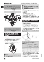
•  Cover the open air intake and discharge with protective

  grilles according to DIN EN ISO 13857.
•  Ensure that the motor has adequate ventilation. Ambient  

  temperature -20°C to +60°C
•  The drive motor ventilation system must not be a

 ected by 

  the installation situation.

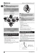
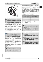
Minimum distance to the blower cover (for the intake of 

cooling air)

Drive power

Minimum distance 

to the blower cover 

[mm]   

[inches]

 1.5 kW

34

1.34

> 1.5 kW

53

2.09

3.2 Electrical connection

Note!

The work described in this section may only be 

performed by a quali

fi

 ed electrician. Connect the 

appliance as per the circuit diagram in the termi-

nal box and in accordance with the relevant local 

requirements.

For devices operated with a frequency converter, the temper-

ature sensor (PTC thermistor) or temperature monitor (break 

contact) must be connected to the converter and inspected.
• Check that the mains voltage matches the ratings on the 

 nameplate.
•  The safety earth terminal can be found in the terminal box.

Note!

The following information should also be ob-

served when operating the drive motor with a 

frequency converter:
• The devices may only be operated with 

frequency converters.
• The frequency converter supply voltage must 

only be a maximum of 400 V without the motor 

fi

 lter. Appropriate measures such as a motor 

fi

 lter 

to protect the motor must be installed on the 

motor terminals with higher frequency converter 

supply voltages, longer lines and/or if the pulse 

voltages are exceeded (max. 1000 Vpk for drive 

motors up to 0.75 kW, maximum 1300 Vpk for 

drive motors larger than 0.75 kW)  Please contact 

the converter supplier in this case. If a motor 

fi

 lter 

is included in the delivery, this must be installed 

between the converter and the motor. Please 

ensure that there is su

  cient space in the switch 

cabinet and take into account the installation and 

assembly requirements in the operating instruc-

tions of the frequency converter/motor 

fi

 lter 

manufacturer.
• The maximum cable length between the mo-

tor and switch cabinet frequency converter (e.g. 

Lenze Vector, Omron MX2 and Omron RX) must 

not exceed 20 m. Maximum cable lengths of up to 

3 m are permitted with Kostal INVEOR frequency 

converters installed close to the motor and up to 

10 m with Lenze MOTEC frequency converters. 

Further information on wall mounting close to the 

motor can be found in the original operating and 

assembly instructions of the respective frequen-

cy converter manufacturer. The electrical con-

necting cables between the motor and frequency 

converter in the above cases must be suitable 

shielded cables, laid using the shortest route and 

without clamping and plug-in connections and 

connected correctly at both sides.
• The shielding braid in the connecting cables 

must be connected fully, continuously and on 

both sides, i.e. to the frequency converter and 

motor, and at low resistance and permanently to 

protective earthing systems or the main earthing 

bus bar. Suitable EMC cable glands must be used 

for this on the motor side and also on the INVEOR 

wall mounting plate, if necessary.
• It is important to ensure that the solid con-

nection of the device to the protective earthing 

system or several suitable earthing lines is at low 

resistance and permanent for blowers installed 

with electrical insulation (e.g. through vibration 

dampers, compensators, insulated pipes, etc.) 

for frequency converter operation.

For further information about EMC compliant installation and 

assembly, refer to the Operating and Assembly Instructions 

issued by the frequency converter manufacturer.
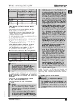
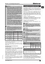
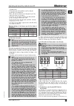
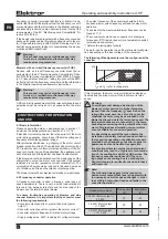
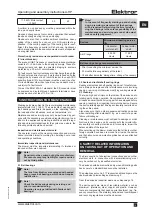
3.3 Con

fi

 guration for three-phase current blowers

Warning!
Danger due to loose or improperly tightened con-

nections!
Improperly tightened and loose connections 

cause electric shocks, 

fi

 res, property damage and 

personal injuries!
Check for loose connections and tighten in 

accordance with the tightening torques in the fol-

lowing table.


 circuit   

                     Y circuit

           (low voltage) 


  (high voltage)

Threaded bolt

Tightening torque

M4

1,2 Nm

M5

2,0 Nm

M6

3,0 Nm

M8

6,0 Nm

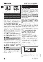
Checking the direction of rotation

Switch on the blower. The running direction of the impeller 

should correspond to the direction arrow on the housing. If 

the impeller rotates in the wrong direction, then interchange 

L1 and L3.

3.4 Declaration concerning the EMC Directive

(2014/30/EU)

Our blowers are components that are designed to be in-

stalled in other machines or systems by quali

fi

 ed personnel, 

i.e. not intended for consumers. The manufacturer of the 

fi

 nal 

system/machine must guarantee/con

fi

 rm that the 

fi

 nal  sys-

tem/machine complies with the EMC Directive.
Prior to the start-up and during operation of the device on a 

Содержание A-HP

Страница 1: ...luminium Hochdruckventilator Betriebs und Montageanleitung DE Aluminum high pressure blower Operating and assembly instructions EN A HP 250 40 A HP 305 30 A HP 330 33 A HP 355 35 A HP 415 35 www elektror com ...

Страница 2: ...20 C bis 80 C nicht überschreiten Son derausführungen mit Temperatursperre bis max 180 C Eine Reihen oder Parallelschaltung von Ventilatoren ist nur nach Rücksprache mit Elektror möglich Der Ventilator ist ohne besondere Maßnahmen nicht für die Auftstellung im Freien geeignet Der Ventilator ist grundsätz lich für S1 Betrieb Dauerbetrieb ausgelegt Davon abwei chend sind maximal 27 Schaltungen pro S...

Страница 3: ...r nehmen damit die gesetzlich zugelassenen Höchstwerte an Arbeitsplätzen in der Umgebung des Ventilators nicht über schritten werden Schalldämmung jeglicher Art darf zu keiner unzulässigen Erhöhung der Umgebungstemperatur über max 40 C am Antriebsmotor führen 1 10 Drehzahlen Warnung Zur Vermeidung von Personenschäden darf die auf dem Motorleistungsschild gestempelte maximale Drehzahl keinesfalls ü...

Страница 4: ...schraube am Motor darf nicht zum Anheben des Gesamtventilators verwendet werden Diese wird für eine evtl Motor de montage verwendet Hinweis Bei Geräten mit aufgebauten Frequenzumrichtern FUK Geräte Der Frequenzumrichter darf keinesfalls zum anheben des Gerätes oder als Steighilfe verwendet werden 2 2 Lagerung Stellen Sie sicher dass der Sauganschluss und der Druck anschluss verschlossen sind Den V...

Страница 5: ...eeignete Maßnahmen wie z B ein Motorfilter zum Schutz des Motors installiert werden Bitte wenden sie sich diesbe züglich an den Umrichterlieferanten Sofern der Motorfilter im Lieferumfang enthalten ist muss dieser zwischen Umrichter und Motor installiert werden Bitte sorgen Sie für ausreichend Platz reserve im Schaltschrank und berücksichtigen Sie die Vorgaben zu Installation und Montage in den Be...

Страница 6: ...sbewertungsverfahren mit den zutreffenden Normen und Richtlinien durchzuführen 4 ANGABEN ZU BETRIEB UND VERWENDUNG 4 1 Grundlegende Hinweise Bitte beachten Sie die unter 1 1 beschriebenen Hinweise zur bestimmungsgemäßen Verwendung sowie die unter 1 2 bis 1 11 beschriebenen Sicherheitshinweise Wenn im Betrieb der Bemessungsstrom des Antriebsmotors überschritten wird prüfen Sie ob Netzspannung und fr...

Страница 7: ...romsensitiver Typ B FI Schutz schalter verwendet werden Der Einsatz eines falschen FI Schutzschalters anders als Typ B kann im Fehlerfall zu Tod oder schweren Verletzungen führen Zur Erfüllung der Norm EN 61800 5 1 muss die Schutzlei terverbindung doppelt über getrennte Klemmen ausgeführt oder einen Schutzleiterquerschnitt mit mindestens 10 mm Cu ausgeführt werden 5 ANGABEN ZUR INSTANDHALTUNG Vers...

Страница 8: ...er wei teren elektrotechnischen Maßnahmen in Verbindung mit der Außerbetriebnahme darf nur von einer Elektrofachkraft aus führt werden Der Abbau ist erst zulässig wenn alle rotierenden Teile den Stillstand erreicht haben und ein Wiederanlauf nicht mehr möglich ist Zum Abbau und Abtransport müssen die Vorgaben aus 2 1 Transport und Handhabung eingehalten werden Behandeln Sie das Gerät bei der Entso...

Страница 9: ... bis festgestellt wurde dass die Maschine in die die unvoll ständige Maschine eingebaut werden soll den Bestimmungen der Maschinenrichtlinie 2006 42 EG entspricht Die folgenden harmonisierten Normen wurden angewandt DIN EN ISO 12100 2011 Sicherheit von Maschinen allgemeine Gestaltungsleitsätze Risikobeurteilung und Risikominimierung DIN EN 60034 1 2011 Drehende elektrische Maschinen Teil 1 Bemessu...

Страница 10: ...n and 180 C in special versions fitted with a thermal barrier Solid particles or contaminants must be removed by a filter unit before entering the blower Series connection or parallel connection of fans is only pos sible after consultation with Elektror The blower is not suitable for installation outdoors without special measures The blower is fundamentally designed for S1 operation continuous ope...

Страница 11: ...0 C at the drive motor this is not permissible 1 10 Speeds Warning The maximum speed stamped on the motor rating plate must never be exceeded in order to prevent personal injury The blower is at risk of mechani cal damage if the speed is exceeded This can cause serious injury or death Each component on the blower has unique natural frequen cies These can be induced by certain blower speeds which m...

Страница 12: ...ts original packaging if possible in a closed room in a dry dust free and vibration free area Storage temperature range from 20 C to 60 C After a storage period of 6 months the blower bearings and or motor bearings should be checked before they are mounted in the blower Devices may be stored for a maximum of 2 years 3 INFORMATION ON COMMISSIONING THE MACHINE 3 1 Installation and assembly Protect t...

Страница 13: ...on MX2 and Omron RX must not exceed 20 m Maximum cable lengths of up to 3 m are permitted with Kostal INVEOR frequency converters installed close to the motor and up to 10 m with Lenze MOTEC frequency converters Further information on wall mounting close to the motor can be found in the original operating and assembly instructions of the respective frequen cy converter manufacturer The electrical ...

Страница 14: ...equency converter operation A frequency converter is used allowing a wide range of speed adjustments There is only a small load related dif ference in rpm between idle state and the max load of the blowers and the lateral channel blower To ensure trouble free operation of blowers and side channel blowers it is important that the converter meet the following requirements Converter output equal to o...

Страница 15: ... ball bearings which do not require relubrication Note Check the ball bearings during servicing and prior to recommissioning Operation is only permitted with flawless ball bearings Note In the event of frequently starting up and shutting down premature replacement of the bearings will be required Determining the time for repla cing the bearings is the sole responsibility of the maintenance and ser...

Страница 16: ... intended use This shall also apply in particular to use in special applica tions and under operating conditions that have not been spe cifically agreed with Elektror Elektror shall not accept any liability for any modifications or alterations to the device or accessories supplied Likewise Elektror shall not be liable for improper delayed neglected maintenance Neither shall it be liable for any cl...

Страница 17: ...ified that the machine in which the partially completed machine is to be installed complies with the provisions of the Machinery Directive 2006 42 EC The following harmonised standards were applied DIN EN ISO 12100 2011 Safety of machinery General principles of design Risk assessment and risk reduction DIN EN 60034 1 2011 Rotating electrical machines Part 1 Rating and performance DIN EN 60034 5 20...

Страница 18: ...ild When ordering please state Serial no rating plate and blower type rating plate Gehäusestellungen Die Gehäusestellung des Ventilators ist für die Bestellung einiger Ersatztei le entscheidend Bestellen Sie Ersatzteile zur Drehrichtung passend Housing positions The position of the blower housing is important for ordering several spare parts Order spare parts which match the direction of rotation ...

Страница 19: ...19 www elektror com 9025316 07 20 05 ...

Страница 20: ...nennung Designation 1 Sechskantmutter ISO 4032 Hexagon nut ISO 4032 2 Scheibe DIN 125 Disc DIN 125 3 Motor Motor 4 Sechskantschraube mit Flansch DIN 6921 Hexagon bolt with fl ange DIN 6921 5 Ventilatorfl ansch Blower fl ange 6 Sechskantschraube ISO 4017 Hexagon bolt ISO 4017 7 Ventilatorgehäuse Blower housing 8 Laufrad Impeller 9 Scheibe Disc 10 Zylinderkopfschraube DIN 7984 Cylinder head screw DI...

Страница 21: ...age Frequency Power consumption Motor output at max permitted speed Weight Sound pres sure level min max 1 Ball bearing designation 2 m min Pa min 1 V Hz A kW kg db A A HP 250 40 140 3 0 15 2 8500 8275 400 140 6 3 3 0 29 0 83 3 86 4 6205 A HP 250 40 140 4 0 26 0 8580 8310 400 140 8 5 4 0 33 0 83 2 89 6 6205 A HP 250 40 140 5 5 39 8 8580 8300 400 140 9 5 5 5 33 0 83 4 89 8 6205 A HP 305 30 120 4 0 ...

Страница 22: ... model no Nominal motor input power V when under pressure at optimal energy effi ciency kW Volumetric fl ow rate at optimal energy effi ciency m3 min Total pressure diff erence at optimal energy effi ciency Pa Revolutions per minute at optimal energy effi ciency Specifi c relationship Information to simplify disassembly recycling or disposal after fi nal decommissioning Information on installation operatio...

Страница 23: ...rehzahlregelung integriert 1 total effi ciency 2 3 refer to rating plate 4 Elektror airsystems gmbh Hellmuth Hirth Str 2 73760 Ostfi ldern Germany Tax number 5933041962 VAT ID No DE 250175973 District Court Stuttgart HRB 210469 5 refer to operating instruction 6 none A variable speed drive must be installed with this blower The requirements for energy effi ciency do not apply to this type of blower Sp...

Страница 24: ...24 www elektror com 9025316 07 20 05 ...

Страница 25: ...25 www elektror com 9025316 07 20 05 ...

Страница 26: ...www elektror com Elektror airsystems gmbh Hellmuth Hirth Str 2 73760 Ostfildern Postfach 1252 73748 Ostfildern Telefon 49 711 31973 0 Telefax 49 711 31973 5000 info elektror de 9025316 07 20 05 ...

Отзывы: