background image

Page 56

EA Elektro-Automatik GmbH

Helmholtzstr. 31-33 • 41747 Viersen

Germany

Fon: +49 2162 / 3785-0

Fax: +49 2162 / 16230

www.elektroautomatik.de

[email protected]

PS 9000 T Series

3.9 

Loading and saving a user profile

The menu “

Profiles

” serves to select between a default profile and up to 5 user profiles. A profile is a collection of 

all settings and set values. Upon delivery, or after a reset, all 6 profiles have the same settings and all set values 

are 0. If the user changes settings or sets target values then these create a working profile which can be saved to 

one of the 5 user profiles. These profiles or the default one can then be switched. The default profile is read-only. 
The purpose of a profile is to load a set of set values, settings limits and monitoring thresholds quickly without 

having to readjust these. As all HMI settings are saved in the profile, including language, a profile change can also 

be accompanied by a change in HMI language.

On calling up the menu page and selecting a profile the most important settings can be seen, but not changed.


► How to save the current values and settings (working profile) as a user profile

1. 

While the DC output is switched off, tap the touch area 

 on 

the main screen

2. 

In the menu page, tap on “

Page 2

” and then on “

Profiles

”.

3. 

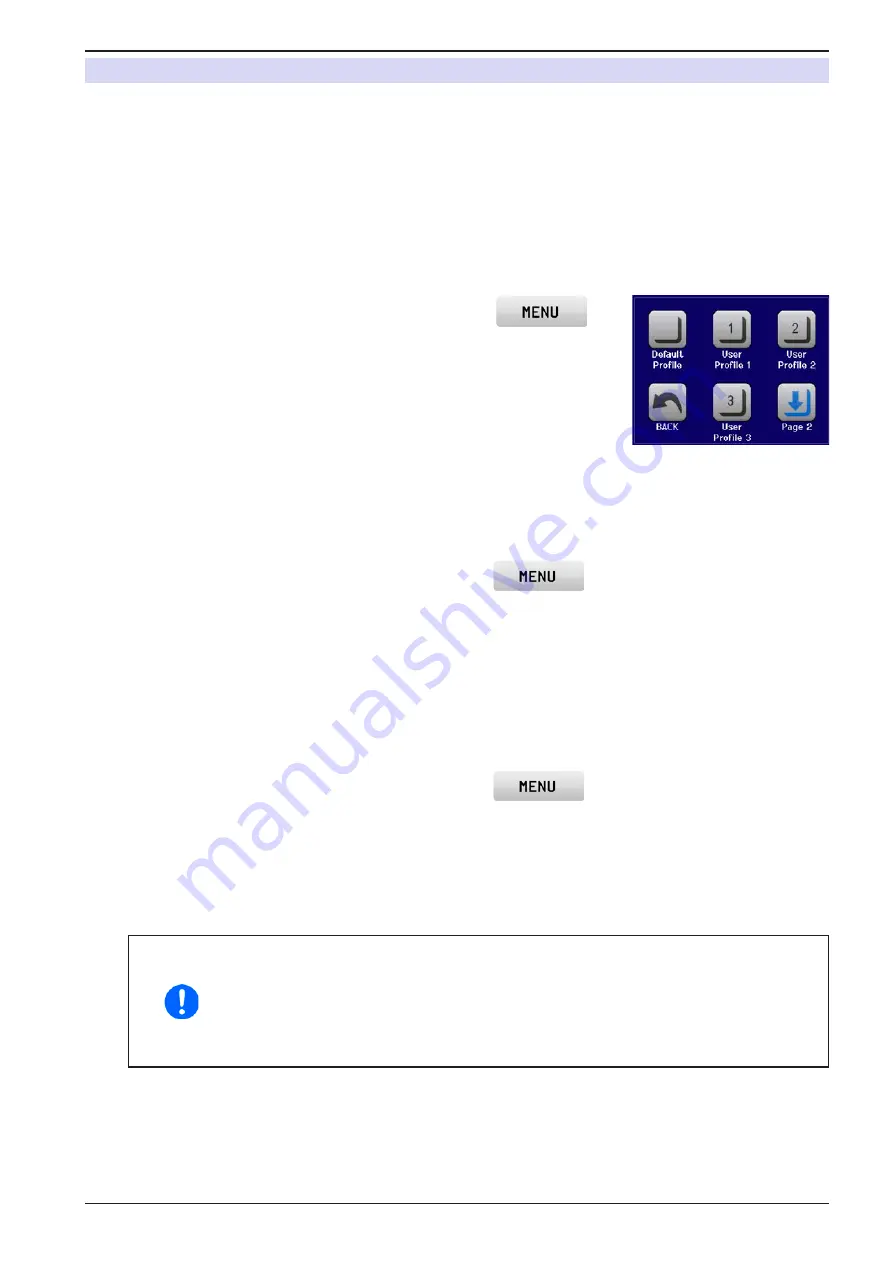
In the selection screen (see image to the right) choose between user 

profiles 1-5 in which the settings are to be saved. The profile will then be 

displayed and the values can be checked, but not changed. 

4. 

Tap on touch area “

Save/Load

” and in the next screen save the user profile 

with touch area “

Save

”.


► How to load a user profile to work with

1. 

While the DC output is switched off, tap the touch area 

 on the main screen

2. 

In the menu page, tap on “

Page 2

” and then on “

Profiles

”.

3. 

In the selection screen (see image to the right) choose between user profiles 1-5 in which the settings are 

to be saved. The profile will then be displayed and the values can be checked, but not changed. 

4. 

Tap on touch area “

Save/Load

” and in the next screen load the user profile with touch area “

Load

”.

User profiles can also be loaded from and saved to a properly formatted USB stick (see section 

1.9.5.5

 for details).


► How to load a user profile from USB stick or save to

1. 

While the DC output is switched off, tap the touch area 

 on the main screen

2. 

In the menu page, tap on “

Page 2

” and then on “

Profiles

”.

3. 

In the selection screen (see image to the right) choose between user profiles 1-5 in which the settings are 

to be saved. The profile will then be displayed and the values can be checked, but not changed. 

4. 

Tap on touch area “

Import/Export

” and in the next screen either save the profile to USB stick by tapping 

on “Save to USB” or load it from the stick with “Load from USB”.

• 

When loading a profile from USB stick it will overwrite all previously stored values of 

the selected user profile

• 

The number in the profile file name is not related to the user profile number from which 

it once was saved or to which is it going to be loaded

• 

The selector for picking a profile file to load can only list the first 10 files in the folder

• 

Profile files are checked for validity upon load to determine if the stored values match 

the device

After a profile has been loaded from USB stick it doesn’t become effective automatically. Like when switching 

between profiles, it requires to load the user profile into the working profile. See above for the steps.

Содержание PS 9000 T Series

Страница 1: ...Elektro Automatik Operating Guide PS 9000 T DC Laboratory Power Supply Doc ID PS9TEN Revision 01 Date 04 2017...

Страница 2: ......

Страница 3: ...2 2 3 8 Connecting the USB port rear side 32 2 3 9 Initial commission 33 2 3 10 Commission after a firmware update or a long period of non use 33 3 OPERATIONANDAPPLICATION 3 1 Personal safety 34 3 2 O...

Страница 4: ...10 T 06200453 1 1 4 Symbols and warnings Warning and safety notices as well as general notices in this document are shown in a box with a symbol as follows Symbol for a life threatening danger Symbol...

Страница 5: ...Construction not printed everywhere T Tower model Maximum current of the device in Ampere Maximum voltage of the device in Volt Series 9 Series 9000 Type identification PS Power Supply always programm...

Страница 6: ...o equipment under power sparking may occur which can cause burns as well as damage to the equipment and to the source ESD regulations must be applied when plugging interface cards or modules into the...

Страница 7: ...responsibilities for operation maintenance and cleaning of the equipment ensure that all employees who use the equipment have read and understood the manual Furthermore the users are to be regularly...

Страница 8: ...device itself due to a defect Critical The device and or the load could be damaged Signal OCP OverCurrent Shutdown of the DC output due to excess of the preset limit Non critical protects the load fr...

Страница 9: ...ge 0 352 W 0 352 W 0 352 W Output capacitance 4760 F 3400 F 720 F Temperature coefficient for set values K Voltage current 100 ppm Voltage regulation Adjustment range 0 40 V 0 80 V 0 200 V Accuracy 1...

Страница 10: ...output U I Control signals DC on off remote control on off Status signals CV OVP OT Galvanic isolation to the device Max 1500 VDC Sample rate of inputs outputs 500 Hz Insulation Output DC to enclosure...

Страница 11: ...4 W 0 704 W Output capacitance 4760 F 3400 F 720 F Temperature coefficient for set values K Voltage current 100 ppm Voltage regulation Adjustment range 0 40 V 0 80 V 0 200 V Accuracy 1 at 23 5 C 0 1 U...

Страница 12: ...m side inlet rear exhaust Ambient temperature 0 50 C Storage temperature 20 70 C Humidity 80 not condensing Standards EN 61010 EN 61326 Overvoltage category 2 Protection class 1 Pollution degree 2 Ope...

Страница 13: ...00 W 0 1100 W Output capacitance 6120 F 6120 F 1020 F Temperature coefficient for set values K Voltage current 100 ppm Voltage regulation Adjustment range 0 40 V 0 80 V 0 200 V Accuracy 1 at 23 5 C 0...

Страница 14: ...mm side inlet rear exhaust Ambient temperature 0 50 C Storage temperature 20 70 C Humidity 80 not condensing Standards EN 61010 EN 61326 Overvoltage category 2 Protection class 1 Pollution degree 2 Op...

Страница 15: ...66 A Overpower protection range 0 1100 W 0 1650 W 0 1650 W Output capacitance 130 F 6120 F 6120 F Temperature coefficient for set values K Voltage current 100 ppm Voltage regulation Adjustment range 0...

Страница 16: ...0 mm side inlet rear exhaust Ambient temperature 0 50 C Storage temperature 20 70 C Humidity 80 not condensing Standards EN 61010 EN 61326 Overvoltage category 2 Protection class 1 Pollution degree 2...

Страница 17: ...ion range 0 220 V 0 550 V Overcurrent protection range 0 27 5 A 0 11 A Overpower protection range 0 1650 W 0 1650 W Output capacitance 1020 F 130 F Temperature coefficient for set values K Voltage cur...

Страница 18: ...de inlet rear exhaust Ambient temperature 0 50 C Storage temperature 20 70 C Humidity 80 not condensing Standards EN 61010 EN 61326 Overvoltage category 2 Protection class 1 Pollution degree 2 Operati...

Страница 19: ...33 41747 Viersen Germany Fon 49 2162 3785 0 Fax 49 2162 16230 www elektroautomatik de ea1974 elektroautomatik de PS 9000 T Series A Control panel with display B Knobs C USB port D DC output E Remote...

Страница 20: ...automatik de ea1974 elektroautomatik de PS 9000 T Series Figure 2 Rear view 320 W 640 W version shown Figure 3 Rear view 1000 W 1500 W version shown F Control interfaces digital analog J Power switch...

Страница 21: ...EA Elektro Automatik GmbH Helmholtzstr 31 33 41747 Viersen Germany Fon 49 2162 3785 0 Fax 49 2162 16230 www elektroautomatik de ea1974 elektroautomatik de PS 9000 T Series Figure 4 Top view Figure 5 S...

Страница 22: ...oltage set value or setting the parameter values in the menu Left knob push selection of the decimal position to be changed cursor for the assigned value Right knob turn adjusting the current or power...

Страница 23: ...standard with a USB port on the back side which can be optionally extended to a 3 way interface with USB Ethernet and a galvanically isolated analog port all retrofittable by the user The configuratio...

Страница 24: ...Schuko plug or UK plug depending on shipping destination 1 x USB cable 1 8 m 1 x USB stick with software and documentation 1 9 4 Optional accessories The below listed optional accessories can be purc...

Страница 25: ...nd power are displayed When the DC output is switched on the actual regulation mode CV CC or CP is displayed in the corresponding area like depicted in the figure above with CC in the red area for cur...

Страница 26: ...on on page 37 1 9 5 3 Pushbutton function of the knobs The rotary knobs also have a pushbutton function which is used in all menu options for value adjustment to move the cursor by rotation as shown 1...

Страница 27: ...a recorded during normal operation in all modes The file layout is identical to the those generated from the Logging feature in EA Power Control The nr field in the file name is automatically counted...

Страница 28: ...ssion speed is set to Auto negotiation and means it can use 10MBit s or 100MBit s 1GB s is not supported Duplex mode is always full duplex If remote control is going to be activated the Ethernet inter...

Страница 29: ...Installation 2 3 1 Safety procedures before installation and use Before connecting to the mains ensure that the supply voltage is as shown on the product label Overvoltage on the AC supply can cause...

Страница 30: ...de ea1974 elektroautomatik de PS 9000 T Series 2 3 3 1 Placement on horizontal standing surfaces The device is designed as a desktop unit and must only be operated on horizontal surfaces which are cap...

Страница 31: ...e cables are long then the cross section must be increased to avoid voltage loss and overheating 2 3 4 1 Possible connections on the DC output The DC output on the front is of type clamp plug and can...

Страница 32: ...The optionally available 15 pole connector Type Sub D D Sub on the rear side is an analog interface To con nect this to a controlling hardware PC electronic circuit a standard plug is necessary not i...

Страница 33: ...ables to be used are of a satisfactory cross section Check if the factory settings of set values safety and monitoring functions and communication are suitable for your intended application of the dev...

Страница 34: ...tion Constant voltage Voltage regulation is also called constant voltage operation CV The DC output voltage of a power supply is held constant on the adjusted value unless the output current or the ou...

Страница 35: ...t power CP keeps the DC output power of a power supply constant if the current flowing to the load in relation to the output voltage and the resistance of load reaches the adjusted value according to...

Страница 36: ...plying power temporarily After cooling down the device will automatically continue to supply power while the condition of the DC output remains and the alarm doesn t require to be acknowledged 3 3 3 O...

Страница 37: ...r off All set values are always saved and restored 3 4 2 Switching off the device On switch off the last output condition and the most recent set values are saved Furthermore a PF alarm power failure...

Страница 38: ...s Overview Page 1 Page 2 Page 7 Enter Page 6 Output Settings Protection Settings OVP OCP OPP Limit Settings General Settings Reset device Allow remote control Yes No DC output after power ON OFF Resto...

Страница 39: ...like with U I for Sine where U A changes to I A etc MENU Communication About HW SW IP Settings 1 IP Settings 2 Logging Enable USB logging Com Timeout Com Protocols Timeout USB RS232 ms 5 65535 SCPI M...

Страница 40: ...974 elektroautomatik de PS 9000 T Series Default profile User Profile 1 User Profile 2 User Profile 3 User Profile 4 User Profile 5 MENU Profiles Backlight English Deutsch Language 60 sec on Always on...

Страница 41: ...as local in the status area on the main display See also section 1 9 5 1 DC output after power ON 1 Determines the condition of the DC output after power up OFF DC output is always off after switching...

Страница 42: ...delivery the device only features an USB port which doesn t require configuration It can be extended by an Ethernet LAN port by installing the optional 3 way interface board IF KE4 After installation...

Страница 43: ...B stick feature Once enabled you can define the log interval multiple steps 500 ms 5 s and choose between Start stop with DC on off or Manual start stop With a properly formatted USB stick also see 1...

Страница 44: ...tary knob is made for 60 s As soon as input is made the backlight returns automatically Furthermore the brightness can be selected in 10 steps HMI Lock See 3 7 Control panel HMI lock on page 55 Status...

Страница 45: ...the touch area for direct input is tapped bottom center The adjustment limits are coupled to the set values It means that the upper limit may not be set lower than the corresponding set value Example...

Страница 46: ...will switch the knob to power adjustment and highlight the power value 3 After successful selection the desired value can be set within the defined limits Selecting a digit is done by pushing the rot...

Страница 47: ...standard status page mode with knobs or by direct input Regulation mode CP is displayed alternatively to CC at the same position 3 4 7 Switching the DC output on or off The DC output of the device ca...

Страница 48: ...ting Manual start stop it is different Logging is then started and stopped only in the MENU in the logging configuration page Soon after logging has been started the symbol indicates the ongoing loggi...

Страница 49: ...otely Activating condition Local causes the following If remote control via the digital interface is active Remote then it is immediately terminated and in order to continue remote control once Local...

Страница 50: ...set values VSEL CSEL PSEL correspond to 0 100 nominal values 0 100 actual values correspond to 0 5 V at the actual value outputs CMON VMON 0 10 V Reference voltage 10 V 0 10 V set values VSEL CSEL PSE...

Страница 51: ...ax 5 mA Short circuit proof against AGND 4 DGND POT Ground for all digi tal signals For control and status signals 5 REMOTE DI Switching internal remote control Remote LOW ULow 1 V Internal HIGH UHigh...

Страница 52: ...REM SB A digital output e g from a PLC may be unable to cleanly pull down the pin as it may not be of low enough resistance Check the specification of the controlling application Also see pin diagram...

Страница 53: ...ocked It can be switched on or off by pushbutton or digital command LOW inverted HIGH inverted DC output will be switched off and locked Later it can be switched on again by toggling the pin During lo...

Страница 54: ...eshold The DC output will be switched off 0 V 1 1 UNom Display analog IF digital IF OCP OverCurrent Protection Triggers an alarm if the DC output current reaches the defined threshold The DC output wi...

Страница 55: ...e HMI by tapping on Tap to unlock within 5 seconds otherwise the pop up will disappear and the HMI remains locked In case the additional PIN code lock has been activated in the menu HMI Lock another r...

Страница 56: ...ser profile to work with 1 While the DC output is switched off tap the touch area on the main screen 2 In the menu page tap on Page 2 and then on Profiles 3 In the selection screen see image to the ri...

Страница 57: ...urrent and hence higher power This can be achieved by connecting all units to the DC load in parallel so the single currents can add There is no support for a balancing between the individual units li...

Страница 58: ...the supplier has been contacted and it is clarified how and where the equipment should be sent the device is in fully assembled state and in suitable transport packaging ideally the original packaging...

Страница 59: ...t conditions are required A measurement device multimeter for voltage with a max error of half the PS s voltage error That measure ment device can also be used to measure the shunt voltage when readju...

Страница 60: ...correct and submit with ENTER 5 Repeat step 4 for the next three steps total of four steps In case you are generally using the remote sensing feature it is recommended to also readjust this parameter...

Страница 61: ...epairs if not otherwise arranged between supplier and customer will be carried out by the manufacturer For this the device must generally be returned to the manufacturer No RMA number is needed It is...

Страница 62: ......

Страница 63: ......

Страница 64: ...EA Elektro Automatik GmbH Co KG Development Production Sales Helmholtzstra e 31 37 41747 Viersen Germany Fon 49 2162 37 850 Fax 49 02162 16 230 ea1974 elektroautomatik de www elektroautomatik de...

Отзывы: