Page 32
EA Elektro-Automatik GmbH
Helmholtzstr. 31-33 • 41747 Viersen
Germany
Fon: +49 2162 / 3785-0
Fax: +49 2162 / 16230
www.elektroautomatik.de
PS 9000 T Series
2.3.6 Connection of remote sensing
•
Remote sensing is only effective during constant voltage operation (CV) and for other regulation
modes the sense input should be disconnected, if possible, because connecting it generally
increases the oscillation tendency.
•
The cross section of the sense cables is noncritical. However, it should be increased with in-
creasing cable length. Clamp terminal
Sense
is suitable for cross section of 0.2 mm² (AWG24)
to 10 mm² (AWG8)
•
Sense cables should be twisted and laid close to the DC cables to damp oscillation. If nec-
essary, an additional capacitor can be installed at the load/consumer to eliminate oscillation
•
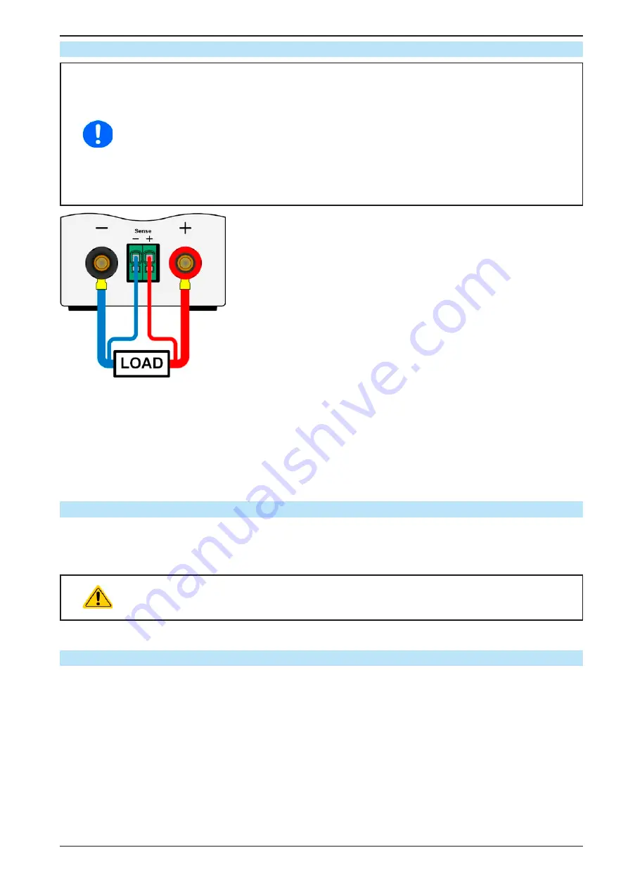
The sense cables must be con to + and - to - at the load, otherwise both systems
may be damaged
Figure 7 - Principle of remote sensing wiring
The connector Sense is a clamp terminal. It means for the remote sensing cables:
•
Insert cables: crimp sleeves onto the cable ends and simply push them into the bigger square hole
•
Remove cables: use a small flat screwdriver and push into the smaller square hole next to the bigger one to
loosen the cable clamp, then remove cable end
2.3.7 Connecting the analog interface
The optionally available 15 pole connector (Type: Sub-D, D-Sub) on the rear side is an analog interface. To con-
nect this to a controlling hardware (PC, electronic circuit), a standard plug is necessary (not included in the scope
of delivery). It is generally advisable to switch the device completely off before connecting or disconnecting this
connector, but at least the DC output.
The analog interface is galvanically isolated from the device internally. Unless absolutely re-
quired, do not connect any ground of the analog interface (AGND) to the DC minus output as
this will cancel the galvanic isolation.
2.3.8 Connecting the USB port (rear side)
In order to remotely control the device via this port, connect the device with a PC using the included USB cable
and switch the device on.
2.3.8.1 Driver installation (Windows)
On the initial connection with a PC the operating system will identify the device as new hardware and will start to
install a driver. The required driver is for a Communications Device Class (CDC) device and is usually integrated in
current operating systems such as Windows 7 or 10. But it is strongly recommended to use and install the included
driver installer (on USB stick) to gain maximum compatibility of the device to our softwares.
2.3.8.2 Driver installation (Linux, MacOS)
We cannot provide drivers or installation instructions for these operating systems. Whether a suitable driver is
available is best found out by searching the Internet. With newer versions of Linux or MacOS, a generic CDC
should be “on board”.


