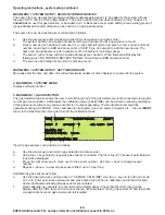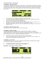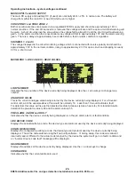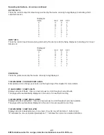
-29-
Operating instructions - fault messages continued
Supply voltage fault
Battery open circuit - please replace / Battery too low to charge - please remove and charge
No response from Loop Card or I/O Card - Comms error.
important to note
Engineer to
visit immediately
Fire
Evacuate
All of the input power supplies to the control unit and also the dc fused output are monitored.
The battery is monitored for open circuit and under voltage. If the system has been running off batteries for
some time it is likely the battery voltage is very low. If when the AC mains is restored the battery voltage is
below approximately 22V the system will not charge the batteries, avoiding high charging currents and
excessive heat generated inside the control unit. The batteries should be removed and charged using a
dedicated battery charger.
The Display, I/O module and Loop cards all communicate with each other. If one of these modules develops a
fault it is possible for this communication to fail. It is also possible for a communications error to occur if the
system is subjected to extreme RFI. In the event of a communications failure the Comms lamp will be
illuminated and the internal buzzers will operate.
The system automatically tries to recover from a comms error and pressing the reset button may restore
communications. If the system is unable to recover removing the power, including the batteries, may solve the
problem. If the communication fault was caused by a hardware failure it will not be possible to recover.
In the event of an internal communications fault:
1.
Press “RESET” on the display module.
or
2.
Turn off the system, wait a few seconds and then turn it back on.
or
3.
If the display module, is still operational, reboot the system. See page 25.
If the above does not allow the system to recover its normal operating condition arrange for an
. Next check the status of the system to establish what functions, detectors etc., are still
operational, as follows:
4.
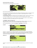
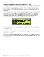
Open the ED816 door, unscrew and remove the top blanking plate to reveal the backup switches and
lamps shown above.
4.
Check the power light is on each module within the system as the fault could be caused by a blown fuse.
If a fuse has blown on any of the ED722 or ED726 Loop modules or the fuse feeding the I/O module has
blown, the Alarm, Pre-Alarm, Fault and Delayed relays, the HWFD output and Sounder 1 will operate.
5.
Test the detectors and other loop devices on each loop and conventional zones, if used, to establish
which devices are still operational.
6.
In the event of a
the loop sounders and beacons can be silenced by pressing both of the “MUTE”
buttons shown above. Similarly Loop devices can be reset by pressing both “RESET” buttons shown
above.
To
press both the “EVACUATE” buttons shown above.
It is
that in the event of a communication fault system operation may be
affected.
Cause and effects programmed may not operate and the display module may not be able to operate correctly.
However if the loop cards are still operational the system will still continue to operate in a limited manner. In the
event of a communications fault the push buttons “EVACUATE”, “MUTE” and “RESET”, located on the ED816A
I/O board, become operational (in normal operation they act only as lamp test buttons).
7.
severely
ED816A Addressable Fire and gas detection Installation manual 8-9-08 Rev-a
Back up alarm / indicator lamps
EVACUATE MUTE
RESET
POWER
ALARM
PRE-ALM
DELAYED
FAULT
SILENCED
ISOLATED
LOOP 1 STATUS
EVACUATE MUTE
RESET
POWER
ALARM
PRE-ALM
DELAYED
FAULT
SILENCED
ISOLATED
LOOP 2 STATUS
Lamp Test button and backup
Reset button.
Lamp Test button and backup
Evacuate button.
Lamp Test button and backup


