+
SOUNDER WIRING
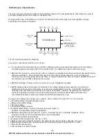
The fault monitored sounder circuits can be used to operate several sounders and beacons up to a
maximum load of 1A. A 4K7 Ohm end of line resistor should be fitted across the last device to facilitate
fault monitoring. Note: SNDR1 is fail safe and should always be used first, with sounders / beacons in
a manned location.
-
+
-
-
-
SND 1
SND 2
+
-
+
-
-
-
SND 1
SND 2
+
-
+
-
4K7
EOL
+VE
-VE
SOUNDER CCT
1,2 OR 3
ED6 SOUNDER
ED6 SOUNDER /
BEACON COMBINATION
ED6 BEACON
Never use looped wire always use separate conductors for input and outputs thus enabling fault
monitoring.
If Sounders and Beacons are not supplied by EDL, ensure they have a series polarity
protection diode fitted. Please contact EDL for further information.
REPEATER WIRING
Up to eight repeaters can be connected to each system. The last repeater on the line must be a type A.
Type A and B repeaters differ only in that type A repeaters have terminating resistors, R2 and R39,
fitted.
Repeaters can be powered by a local, battery backed, 24Vdc supply or driven off the fused output
terminals provided in the ED816A. Each repeater draws a maximum of 350mA.
The data cable used should be 2 conductor (twisted) 124 Ohm twinixial 25 AWG (0.16 sq mm) with foil
screen and drain wire. E.g. Beldon 9271 006 (BLULT).
With full duplex wiring each repeater has exactly the same functionality as the main control panel, giving the
designer the option of using the repeater as the main interface. This allows the control panel to be situated in a
more central location.
It is possible to operate repeaters without their full functionality by omitting the repeater transmit wiring; i.e.
Wiring between Z, Y (repeater) and A, B (control panel).Thus the repeater can only receive information, no
information can be transmitted to the control panel including setup information etc.. Electronic Devices Limited
do not recommend this method because the EVAC button on the repeater will not function. However a solution
is to have a call point located next to the repeater set to “no zone”. Call points set to no zone automatically
operate the evacuate command when operated.
It is for this reason all repeaters installed should be checked
they both transmit data as well as receive it from the control panel.
SCRN
B
A
SCRN
Z
Y
SCRN
Z
Y
SCRN
B
A
SCRN
Z
Y
SCRN
B
A
SCRN
Z
Y
SCRN
B
A
24V FUSED
OUTPUT
+
-
RS485FULL
DUPLEX
+
-
+
-
+
-
CONTROL PANEL
REPEATER
TYPE B
REPEATER
TYPE B
REPEATER
TYPE A
RX
TX
TX
RX
TX
RX
TX
RX
-12-
ED816A Addressable Fire and gas detection Installation manual 8-9-08 Rev-a

