background image

Installation - electric, steam and gas heating

487 18 39 01 - 300/500/750 - GB

32

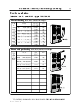
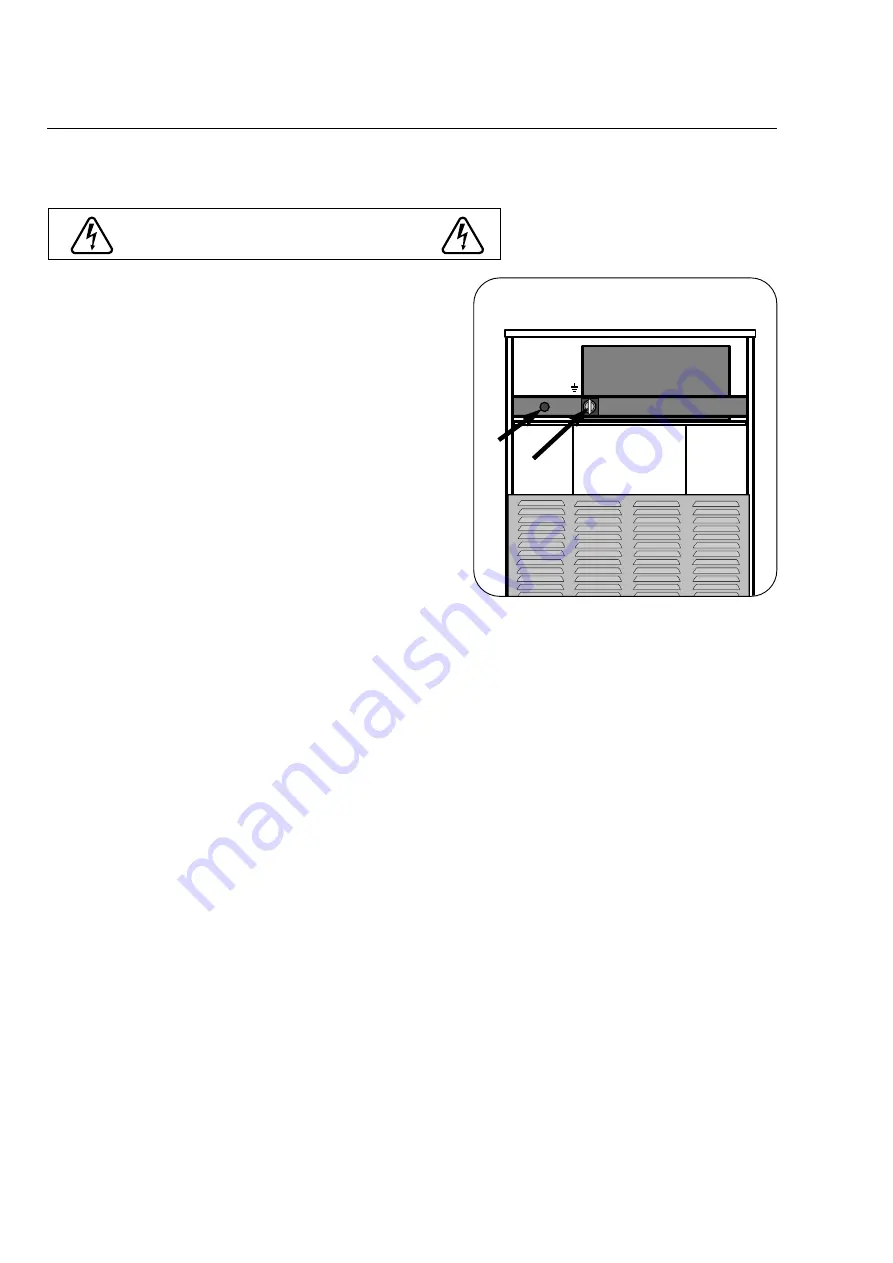
Electric installation 750/75/650

To be carried out by qualified personnel

The tumble dryer must be given a fuse group of
its own.

Connecting the cable: 

Remove the top plate at the back of the tumble
dryer to connect the cable through cable glands A
to locking power switch clamp or to terminal
strip C.

Interlockable switch B is mounted on machines for

countries within EU and EEA (as provided for in
the directive on mechanical engineering regarding
power switches for electrical supply during servic-
ing work).

Cable dimension:

For calculation of the connection cable dimen-
sion, please refer to local guidelines.

Fuse size  and effect are given on the pages to follow.

Function check, see next page. 

(NB: Correct direction of rotatio

is important!)

The tumble dryer must be equipped with sup-
plementary protection in accordance with
heavy current regulations.

L3 L2 L1 N

B

A

C

Содержание TT300

Страница 1: ...Operating and installation manual TT300 TT500 TT750 487 1839 51 01 99 31 ...

Страница 2: ......

Страница 3: ...ELL GAS Do not try to light any appliance Do not touch any electrical switch do not use any phone in your building Clear the room building or area of all occupants Immediately call your gas supplier from a neighbour s phone Follow the gas supplier s instructions If you cannot reach your gas supplier call the fire department Installation and service must be performed by a qualified installer servic...

Страница 4: ......

Страница 5: ...The manufacturer reserves the right to modify design and material specifications without notice Tumble dryer Safety instructions This machine is only intended for drying water washed gar ments The machine must not be used for drying foam rubber or foam like materials The machine must not be used for drying floor mops The machine must not be used by children The machine must not be hosed down with ...

Страница 6: ......

Страница 7: ...Instructions for use 7 487 18 39 01 300 500 750 GB Diagram of tumble dryer Door Drum Filter door Operating panel ...

Страница 8: ...e H Temperature I Gasheated Push button with light indicator for resetting gas control On machine with reversing J Reversing switch a With reversing b Without reversing Warning If the gas flame is not ignited within 10 seconds after starting the tumble dryer the gas con trol will automatically turn off the gas and report an error Push button I will be lit After 15 seconds it is possible to reset t...

Страница 9: ...ents may fall out when the door opens The last few minutes of the drying time are the cooling down period the garments are cooled To prevent creasing Empty the tumble dryer as soon as the program has ended If the tumble dryer is not emptied immediately after the drying time has ended an anti crease programme is automatically engaged This means that the drum rotates at short intervals thereby almos...

Страница 10: ...cate selected temperature H Temperature I Gasheated Push button with light indicator for resetting gas control On machine with reversing J Reversing switch a With reversing b Without reversing 1 2 4 5 3 3 15 90 MIN 15 90 MIN Warning If the gas flame is not ignited within 10 seconds after starting the tumble dryer the gas con trol will automatically turn off the gas and report an error Push button ...

Страница 11: ...als thereby almost completely avoiding creasing To prevent creasing Empty the tumble dryer as soon as the program has ended High 70 85 C non iron normal wash cotton and mixed fabrics Drying at normal heat Low 50 C Fine wash mild wash Delicate fabrics Drying at low heat No heat suitable for airing bedspreads duvets and bedclothes etc 85 C 70 C 50 C Select tempe rature 15 90 MIN Select the program P...

Страница 12: ...Filter when the lamp is lit the filter must be cleaned C Lamps lit to indicate selected temperature D Temperature E Coin insertion one ore double insertion F Operating lamp G Timer button not active on coin operated machines H Start stop button I Temperature selection button J Jammed coin return button K Returned coins Coin operation ...

Страница 13: ...e fabrics Drying at low heat No heat suitable for airing bedspreads duvets and bedclothes etc 85 C 70 C 50 C Select temperature Stop Press the start stop button or open the door Take care Garments may fall out when the door opens Restart Close the door again and press the start stop button The last few minutes of the drying time are the cooling down period the garments are cooled To prevent creasi...

Страница 14: ... on machines controlled by a central control panel C Operating lamp indicator Ready to start D Timer button not active on payment machines E Start stop button F Temperature selection button G Lamps lit to indicate selected temperature H Temperature 1 2 3 4 5 G H A D E F B C Machine controlled by a central control panel CP ...

Страница 15: ...gram has ended If the tumble dryer is not emptied immediately after the drying time has ended an anti crease programme is automatically engaged This means that the drum rotates at short intervals thereby almost completely avoiding creasing The tumble dryer stops automatically when the paid drying time has ended Restart Close the door again and press the start stop button When the lamp flashes the ...

Страница 16: ...s It is not necessary to remove the lint fil ter for cleaning The air system of the machine ensures that lint and dust settle automatically at the bottom of the filter compartment from where they are removed by means of a hand held broom or a vacuum cleaner Check that the lint filter is unbroken Quarterly Semi annually Check that the fresh air intake at the back of the machine is not clogged by li...

Страница 17: ... year a skilled expert should check the inside wearing parts of the machine and clean them of lint Lubrication The motor bearings idler bearings and main bearings are permanently lubricated No lubrication is necessary Maintenance only for steam heating Cleaning the filter in front of steam battery Open the front panel Remove the filter as shown A Clean the filter with water or with compressed air ...

Страница 18: ...Instructions for use 18 487 18 39 01 300 500 750 GB ...

Страница 19: ...al installation Adjust the machine to make it stand horizontally and stably on all four feet The max height adjustment of the feet is 15 mm 2 3 10 Reversing door The tumble dryer is usually delivered with a right hinged door but the door can easily be changed to left hinged position Reversing Disconnect the power supply to the machine Unscrew the door and the front panel Move the microswitch and t...

Страница 20: ...the pallet to be pulled out from beneath it Put the tumble dryer into position tipping it up to allow the four supplied feet to be fitted Positioning Position the tumble dryer so that there is plenty of room for working both for the user and for the service technician The distance from the wall or other equipment behind the tumble dryer should be at least 500 mm and the space at the sides at least...

Страница 21: ...ehind the machine The area of the air inlet opening must be 5 times the size of the vent pipe area The resistance in the grating slats should not exceed 10 Pa 0 1 mbar 300 30 The air consumption is approx 430 925 m3 h 500 50 The air consumption is approx 840 1380 m3 h 750 75 650 The air consumption is approx 1500 m3 h The area of the inlet opening is the area through which the air can flow without...

Страница 22: ...rm how the evacuation pipe should look Note To keep the air flowing use bends not T pieces See Fig 1 1 2 3 4 5 6 7 8 9 10 200 280 315 355 400 450 475 500 535 560 0 15 0 30 0 45 0 60 0 75 0 90 1 05 1 20 1 35 1 50 Number of tumble dryers Air outlet pipe diameter mm Required area of fresh air inlet m2 Tumble dryer evacuation system Evacuation system for installation of several machines with a shared ...

Страница 23: ... and impurities Note In cold areas condensation may cause frost damage to the building In case of queries relating to the design of the air evacuation system please contact our ser vice organisation dealer Air principle The ventilator creates low pressure in the drum drawing air into the machine via the heating unit The heated air passes through the garments and the drum vents Then the air flows o...

Страница 24: ...m of flashing error codes F1 Setting of machine type and variety is missing F1 is shown while the print board is being changed or if the power is connected to the machine while the service program is active Machine type and variety should be set in the ser vice program F4 The thermal sensor is disconnected Loose or broken connection ...

Страница 25: ...ine off and on again After approx 10 seconds the first two digits of a 6 digit number 01 are shown and at the same time lamp A lights up After 4 seconds the lamp and the two digits are turned off After a two second pause the next two digits 27 show while lamp B is lit After 4 seconds the lamp and the two digits are turned off After a two second pause the last two digits 96 are shown with lamp C li...

Страница 26: ...General installation 487 18 39 01 300 500 750 GB 26 ...

Страница 27: ...opening G Steam connection F M Electric and gas connections L Electric and steam connections 300 30 500 50 750 75 650 Ø 580 Ø 810 A B C D E F G H 300 30 710 1120 1880 780 725 1610 470 135 500 50 960 1180 1995 720 650 1725 595 155 750 75 650 960 1370 1995 720 650 1725 595 155 I J K L M N O P 300 30 170 710 1810 1380 250 500 50 225 960 2120 1510 270 750 75 650 225 960 2300 1510 270 ...

Страница 28: ... 1680 rpm Effect of drum motor 0 37 kW Effect of fan motor 0 37 kW Drum motor revolutions 50 Hz 1400 rpm Drum motor revolutions 60 Hz 1680 rpm Fan motor revolutions 50 Hz 1400 rpm Fan motor revolutions 60 Hz 1680 rpm Heat effect Electric heating 13 5 kW Electric heating 18 0 kW Gas heating 21 0 kW Air consumption Electric 13 5 kW 430 m3 h Electric 18 0 kW 690 m3 h Steam 925 m3 h Gas 690 m3 h Pipe ...

Страница 29: ...37 kW Drum motor revolutions 50 Hz 1400 rpm Drum motor revolutions 60 Hz 1680 rpm Fan motor revolutions 50 Hz 1400 rpm Fan motor revolutions 60 Hz 1680 rpm Heat effect Electric heating 24 0 kW Electric heating 30 0 kW Gas heating 40 0 kW Air consumption Electric 24 0 kW 840 m3 h Electric 30 0 kW 1060 m3 h Steam 1380 m3 h Gas 1160 m3 h Pipe connection Evacuation Ø 200 Ø 200 Ø 200 Steam ISO 7 1 Rp 3...

Страница 30: ...pm 1400 rpm Drum motor revolutions 60 Hz 1680 rpm 1680 rpm 1680 rpm Fan motor revolutions 50 Hz 2800 rpm 2800 rpm 2800 rpm Fan motor revolutions 60 Hz 3300 rpm 3300 rpm 3300 rpm Heat effect Electric heating 30 0 kW Electric heating 36 0 kW Gas heating 57 0 kW Air consumption Electric 30 0 kW 1500 m3 h Electric 36 0 kW 1500 m3 h Steam 1500 m3 h Gas 1500 m3 h Pipe connection Evacuation Ø 200 Ø 200 Ø...

Страница 31: ...to terminal strip C Cable dimension For calculation of the connection cable dimen sion please refer to local guidelines Fuse size and effect are given on the pages to follow Function check see next page NB Correct direction of rotation is important The tumble dryer must be equipped with sup plementary protection in accordance with heavy current regulations Electric installation 300 30 500 50 To be...

Страница 32: ...strip C Interlockable switch B is mounted on machines for countries within EU and EEA as provided for in the directive on mechanical engineering regarding power switches for electrical supply during servic ing work Cable dimension For calculation of the connection cable dimen sion please refer to local guidelines Fuse size and effect are given on the pages to follow Function check see next page NB...

Страница 33: ... door is opened as much as 50 mm The direction of rotation should be clockwise see illustration If the direction is reversed shift two phases Let the machine work for 5 minutes on a program that requires heat Then check whether the heat ing is working by opening the front door to check if heat can be felt If the above test points are found to be in order the tumbler is ready for use If deficiencie...

Страница 34: ...r 1 5 kW 10A heating 230 240V 3AC 50 60 Hz 13 5 kW 40A motor 1 5 kW 10A heating 230 240V 3AC 50 60 Hz 18 0 kW 50A motor 1 5 kW 10A Voltage Heat and motor effect Fuse Only one cable for con trol and motor Steam and gas heating fuse sizes effects and voltages 400V 3NAC 50 60 Hz 1 5 kW 10A 400 440V 3AC 50 60 Hz 1 5 kW 10A 230 240V 3AC 50 60 Hz 1 5 kW 10A 230 240V 1AC 50 60 Hz 1 5 kW 10A Voltage Total...

Страница 35: ...0 kW 10A heating 230 240V 3AC 50 60 Hz 24 0 kW 2 x 40A motor 2 0 kW 10A heating 230 240V 3AC 50 60 Hz 30 0 kW 2 x 50A motor 2 0 kW 10A Voltage Heat and motor effect Fuse Only one cable for con trol and motor Steam and gas heating fuse sizes effects and voltages 400V 3NAC 50 60 Hz 2 0 kW 10A 400 440V 3AC 50 60 Hz 2 0 kW 10A 230 240V 3AC 50 60 Hz 2 0 kW 10A 230 240V 1AC 50 60 Hz 2 0 kW 10A Voltage T...

Страница 36: ... 3AC 50 60 Hz 31 3 kW 100A 230 240V 3AC 50 60 Hz 37 3 kW 100A Voltage Total output Fuse Within the EU and EEA type 750 75 650 Only one cable for con trol and motor Steam and gas heating fuse sizes effects and voltages 400V 3NAC 50 60 Hz 2 0 kW 10A 400 440V 3AC 50 60 Hz 2 0 kW 10A 230 240V 3AC 50 60 Hz 2 0 kW 10A 230 240V 1AC 50 60 Hz 2 0 kW 10A Voltage Total output Fuse Electric installation Elect...

Страница 37: ...eating 230 240V 3AC 50 60 Hz 30 0 kW 2 x 50A motor 1 3 kW 10A heating 230 240V 3AC 50 60 Hz 36 0 kW 2 x 50A motor 1 3 kW 10A Voltage Heat and motor effect Fuse Outside the EU and EEA type 750 75 650 Only one cable for con trol and motor Steam and gas heating fuse sizes effects and voltages 400V 3NAC 50 60 Hz 2 0 kW 10A 400 440V 3AC 50 60 Hz 2 0 kW 10A 230 240V 3AC 50 60 Hz 2 0 kW 10A 230 240V 1AC ...

Страница 38: ...Installation electric steam and gas heating 487 18 39 01 300 500 750 GB 38 ...

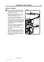
Страница 39: ...and outlet hoses E on the battery To prevent the inlet and outlet connecting branches from being deformed it is important to support them using an extra open end wrench Then connect the steam installation to the other end of the steam hoses E using the accompanying counter flanges F Just after the outlet flange F mount a dirt collector D After the dirt collector place a mechanical water discharger...

Страница 40: ...should not be allowed to sag see fig 3 since this would create local accumulations of condensate leading to a risk of water shock in the steam battery Since hoses are used after the battery a continu ous slope must also here be ensured all the way to the water discharger All pipes should be insulated to reduce the risk of burns while also reducing the heat loss to the surroundings Steam Water stea...

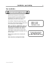
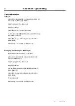
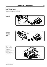
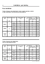
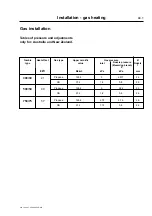
Страница 41: ...n on the nameplate NB If converting to a different type of gas an appropriate sign supplied must replace the existing plate on the back of the machine Check that the nozzle pressure and fuel value agree with the values given in the table If not con tact the supplier Bleed the pipe system before connecting the machine After connection test all joints for leaks For gas valves pressure and adjustment...

Страница 42: ...lator under nipple 3 Check that the gas is burning evenly and with a bluish flame After testing prepare the machine for use Changing to natural gas bottled gas Mount the supplied nozzle 1 see table Connect a manometer to measuring branch 2 See gas valve pages Select a program that uses heat Start the machine Set the nozzle pressure using adjusting screw 4 under nipple 3 Check that the gas is burni...

Страница 43: ...Installation gas heating 487 18 39 01 300 500 750 GB 43 2 4 3 1 Nozzle 2 Measuring branch 3 Nipple 4 Adjusting screw Type 300 30 500 50 750 75 650 300 30 500 50 750 75 650 Gas valve 1 1 Gas installation ...

Страница 44: ...40 57 kW 300 30 21 Tables of pressure and adjustments only for english speaking countries except Great Britan Eire Australia and New Zealand Upper calorific value Gas installation Gas type Gas pressure Ø Inlet Nozzle 1 MJ m3 mbar mbar mm LPG 125 81 28 37 28 37 2 2 GNH 37 78 20 10 5 3 8 LPG 125 81 28 37 28 37 3 2 GNH 37 78 20 8 5 6 LPG 125 81 28 37 28 37 3 8 GNH 37 78 20 9 5 6 5 Nozzle pressure Mea...

Страница 45: ...a mm Propane 126 4 3 2 577 2 4 GN 37 4 1 8 0 8 4 0 Propane 126 4 3 2 44 3 5 GN 37 4 1 8 0 8 5 6 Propane 126 4 2 75 2 75 3 8 GN 37 4 1 15 0 8 6 5 Nozzle pressure Measuring branch 2 Tumble type Heat effect 500 50 750 75 40 57 kW 300 30 21 Tables of pressure and adjustments only for Australia and New Zealand Upper calorific value ...

Страница 46: ...Installation electric steam and gas heating 487 18 39 01 300 500 750 GB 44 2 ...

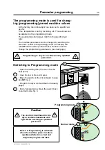
Страница 47: ...e dryer as described on following pages End of programming Move the switch back to normal mode fig 3 1 2 2 3 3 The programming mode is used for chang ing programming preset machine values At the factory the tumble dryer has been set to specific val ues for Time temperature cooling reversing etc These values can be adjusted in the programming mode The parameters shall always match to the specific d...

Страница 48: ...coin 2 07 Running time between reversals 08 Cooling time 09 11 Residual moisture levels 12 14 Extra drying time Adjustable parameters Change of machine type Press the clock button the display will read 00 which is the first parameter first parameter 00 machine type The parameter numbers are shown for two seconds with a dot after the last digit After two seconds the machine type selected will be di...

Страница 49: ...up down buttons etc It is possible to scroll the parameters by pushing the clock button repeatedly The machine type can be changed by using the buttons to count up or down Machine type 300 500 750 650 w o reversing 10 50 11 51 12 300 500 750 650 w reversing 30 70 31 71 32 Coin Manual RMC Central control panel Manual control of time 51 and 71 are specially designed for the Japanese market Machine t...

Страница 50: ...coin 2 Max running time on manual machine or running time per coin insert on coin 2 double insert Temperature program Low Can be set to a value between 01 C 10 C Factory setting 02 Can be set to a value between 0 1 and 90 minutes Factory setting 15 Lowest temperature can be set to a value between 32 C 85 C Factory setting 50 From 0 1 to 9 9 minutes the setting can be changed by increments of 1 10 ...

Страница 51: ... 00 and 10 minutes Factory setting 03 Can be set to a value between 05 and F0 Factory setting F0 Can be set to a value between 05 and F0 Factory setting F0 Can be set to a value between 05 and F0 Factory setting 30 Can be set to a value between 00 and 20 minutes Factory setting 09 Can be set to a value between 00 and 20 minutes Factory setting 03 Can be set to a value between 00 and 20 minutes Fac...

Страница 52: ...increments The values for residual moisture are shown in the display in so called hexadecimals a series of numbers covering a total of 16 values for each digit 0 1 2 3 9 A B C D E F A total of 236 values can be shown Example P3 ironing dry parameter no 11 30 If the clothes are not dry enough add increments by using the count up button 31 32 33 34 3A 3b 3C 3d etc up to F0 P3 0 03 09 minutes Paramet...

Страница 53: ... 5 0 5 0 Running time between reversals 08 03 03 03 03 Cooling time 09 F0 Moisture level P1 extra dry 10 F0 Moisture level P2 ready to put away 11 30 Moisture level P3 ironing dry 12 09 Extra drying time P1 13 03 Extra drying time P2 14 00 Extra drying time P3 Payment machines Parameters 09 14 cannot be set Will run without payment bypassing the control panel if the machine code is set to 43 CP Co...

Отзывы: