


8
2.2 Technical data
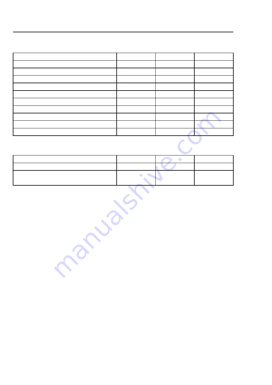
T5130
T5130C
Weight, net
kg
54
57
Drum volume
litres
130
130
Drum diameter
mm
575
575
Drum depth
mm
500
500
Drum speed
rpm
53
53
G-factor, max.
0.9
0.9
Rated capacity, filling factor 1:22 (Max. load)
kg
6
6
Heating: Electricity
kW
5.1
3.0
kW
3.2
Airborne sound level
dB(A)
70
70
2.3 Connections
T5130
T5130C
Air outlet
⌀
mm
100
—
Condensate outlet
-
1/2"
ISO 7/1–Rp1/2
Содержание T5130
Страница 2: ......
Страница 22: ...22 Door Replacement of door magnets Remove the magnet to be replaced and mount the new one fig 7459 ...
Страница 93: ......