


Component Teardown
6-11
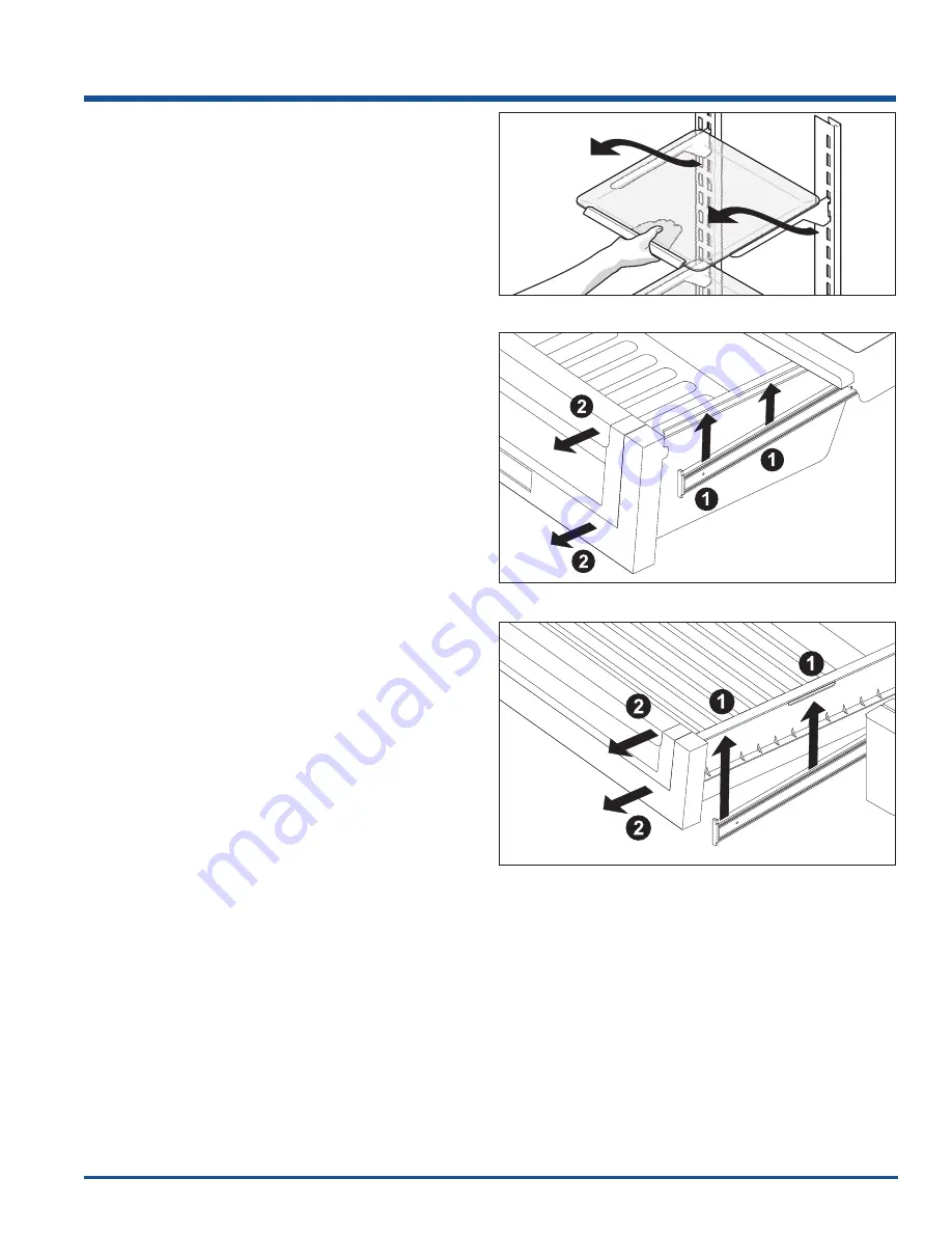
Figure 6-34.
Figure 6-35.
Figure 6-33.
Interior Components
Half and Full Spill Safe
™
Shelf Removal
The shelves have mounting brackets that attach to
slotted supports at the rear of each compartment.
To change the position of a shelf:
1. Before adjusting a shelf, remove all food.
2. Lift the front edge up and pull the shelf out.
(See Figure 6-33)
3. Replace by inserting the mounting bracket hooks
into the desired support slots.
4. Lower the shelf and lock into position.
Deli Keeper and Crisper Removal
Crisper drawers include a sliding control for adjusting
the humidity inside the crisper. This feature can extend
the life of certain fresh vegetables that keep longer in
high humidity.
To remove the crisper drawer:
1. Pull the drawer out until it stops.
2. Lift the front slightly and remove the drawer.
(See Figure 6-34)
Perfect Temp Drawer
™
Removal
The power to operate the drawer as well as a wire from
the food compartment light switch, connects to the
control unit by a wire harness coming out through the
liner. This harness will connect to the 4 pin connector in
the bottom right back section of the control unit.
The wiring harness coming from the user interface
control in the cover will connect to a 8 pin connector
located in the top right side toward the front of the
control unit.
The cover over the drawer contains the User Interface
(UI) board and touch control. The NTC thermistor that
senses the drawer temperature is part of the wiring
harness that runs between the user interface and the
main control unit.
To remove the Perfect Temp drawer:
1. Pull the drawer out until it stops.
2. Lift the front slightly and remove the drawer.
(See Figure 6-35)
Содержание 5995502399
Страница 2: ......
Страница 56: ...Ice Maker Fresh Food Compartment 4 8 Flow Chart No Ice 1 ...
Страница 57: ...Ice Maker Fresh Food Compartment 4 9 Flow Chart No Ice 2 ...
Страница 58: ...Ice Maker Fresh Food Compartment 4 10 Flow Chart No Ice 3 ...
Страница 59: ...Ice Maker Fresh Food Compartment 4 11 Flow Chart No Ice 4 ...
Страница 60: ...Ice Maker Fresh Food Compartment 4 12 Flow Chart No Ice 5 ...
Страница 61: ...Ice Maker Fresh Food Compartment 4 13 Flow Chart No Ice 6 ...
Страница 62: ...Ice Maker Fresh Food Compartment 4 14 Flow Chart Test 48C ...
Страница 63: ...Ice Maker Fresh Food Compartment 4 15 Flow Chart Test 49C ...
Страница 64: ...Ice Maker Fresh Food Compartment 4 16 Flow Chart Test 50C ...
Страница 65: ...Ice Maker Fresh Food Compartment 4 17 Flow Chart 51C ...
Страница 66: ...Ice Maker Fresh Food Compartment 4 18 Flow Chart 52C ...
Страница 67: ...Ice Maker Fresh Food Compartment 4 19 Flow Chart 54C ...
Страница 68: ...Ice Maker Fresh Food Compartment 4 20 Flow Chart 55C ...
Страница 69: ...Ice Maker Fresh Food Compartment 4 21 Flow Chart 56C ...
Страница 70: ...Ice Maker Fresh Food Compartment 4 22 Flow Chart 57C ...
Страница 71: ...Ice Maker Fresh Food Compartment 4 23 Flow Chart 58C ...
Страница 72: ...Ice Maker Fresh Food Compartment 4 24 Flow Chart 59C ...
Страница 73: ...Ice Maker Fresh Food Compartment 4 25 Flow Chart 60C ...
Страница 74: ...Ice Maker Fresh Food Compartment 4 26 Flow Chart 61C ...
Страница 75: ...Ice Maker Fresh Food Compartment 4 27 Flow Chart 62C ...
Страница 76: ...Ice Maker Fresh Food Compartment 4 28 Flow Chart 63C ...
Страница 77: ...Ice Maker Fresh Food Compartment 4 29 Flow Chart ICE t3 Error ...
Страница 92: ...Ice Maker Freezer Compartment 4 44 Step 7 Step 8 Step 9 Step 10 ...
Страница 93: ...Ice Maker Freezer Compartment 4 45 Ice Maker Exploded View For Component Teardown Procedures See Section 6 ...
Страница 94: ...Ice Maker Freezer Compartment 4 46 Notes ...
Страница 97: ...Water System 5 3 Standard Depth Water Schematic Counter Depth Water Schematic ...
Страница 166: ...9 1 Wiring Schematics ERF2500 Control Schematic ...
Страница 167: ...Wiring Schematics 9 2 PTD Board Ice and Water Module and LED Power Board ...
Страница 168: ...Wiring Schematics 9 3 Icemaker Control Board ...
Страница 169: ...Wiring Schematics 9 4 YELLOW YELLOW YELLOW Freezer Compartment Ice Maker Schematic ...
Страница 170: ...Wiring Schematics Diagram 2419559 Rev C ...
Страница 171: ...Wiring Schematics Diagram 2419801 Rev C ...
Страница 172: ...Wiring Schematics Non Dispenser Models Diagram 242046100 Rev A ...
Страница 173: ...Wiring Schematics Non Dispenser Models Diagram 242046700 Rev A ...


