54
Installation manual
18 Note about the A.C. power
According to the EN 60204-1:1997 standard, the machine is provided for A.C. supplies corresponding to the ex-
tracted characteristics below :
4.3.2 A.C. supplies
Voltage:
Steady state voltage: from 0.9 to 1.1 of nominal voltage.
Frequency:
from 0.99 to 1.01 of nominal frequency continuously.
from 0.98 to 1.02 short time.
Harmonics:
Harmonic distortion not to exceed 10 % of the total r.m.s. voltage between live conductors for the sum of the second
through to the fifth harmonic. An additional 2 % of the total r.m.s. voltage between live conductors for the sum of the
sixth through to the 30th harmonic is permissible.
Voltage unbalance:
Neither the voltage of the negative sequence component nor the voltage of the zero sequence component in three-
phase supplies shall exceed 2 % of the positive sequence component.
Voltage interruption:
Supply interrupted or at zero voltage for not more than 3 ms at any random time in the supply cycle. There shall be
more than 1 second between successive interruptions.
Voltage dips:
Voltage dips shall not exceed 20 % of the peak voltage of the supply for more than one cycle. There shall be more
than 1 second between successive dips.
19 Feeder cable sections
The feeder cable sections mentioned in our literature are given only as a guide.
To obtain a value perfectly suited to your own application and which takes account of the different correction factors
in respect of your plant, refer to the tables below.
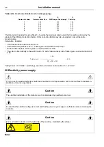
Table 1 (in accordance with EN Standard 60204-1)
Values given for:
• Cable with copper conductors
• Cable with PVC insulation (for other insulants see Table 3)
• Ambient temperature 40°C max. (for others see Table 2)
• Three-phase cable under load without including starting currents
• BT / C/ E cable layout.
Maximum Admissible Current
Cable section
Seated in Cable Duct or
Cable trough
Wall fixing
Cable tray
B2
BC
E
3 x 1.5 mm²
12.2 A
15.2 A
16.1 A
3 x 2.5 mm²
16.5 A
21 A
22 A
3 x 4mm²
23 A
28 A
30 A
3 x 6 mm²
29 A
36 A
37 A
3 x 10 mm²
40 A
50 A
52 A
3 x 16 mm²
53 A
66 A
70 A
3 x 25 mm²
67 A
84 A
88 A
3 x 35 mm²
83 A
104 A
114
3 x 50 mm²
-
123 A
123 A
3 x 70 mm²
-
155 A
155 A
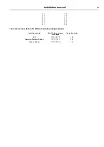
Table 2 (correction factors for different ambient temperatures)
Ambient temperature
Correction factor
30 °C
1.15
Содержание WP4 1100H
Страница 1: ...Installation manual Washer extractors WP4 WPB4 700 900 1100H original instructions 05201052 EN ...
Страница 2: ......
Страница 4: ......
Страница 25: ...Installation manual 25 6 3 Washer extractor type 900 One door WP4 900H Drawing 07100138 ...
Страница 31: ...Installation manual 31 6 5 Washer extractor type 1100 One door WP4 1100H Drawing 07100136 ...
Страница 53: ...Installation manual 53 ...
Страница 66: ......
Страница 67: ......
Страница 68: ...Electrolux Professional AB 341 80 Ljungby Sweden www electroluxprofessional com ...

