01/10/2008 8
HI321
Important
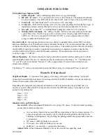
- Located on the WF II board is a firmware chip that determines a specific set of defaults (see
table below). However, this can be programmed (altered) with optional PC software (ET-SOFT-WF) or a
plug-in WarmFlo analyzer (WF-ANZ*). As part of the WF II system this chip represents critical defaults
and settings that make your system operate correctly. It is a critical portion of the installation to verify
that the chip code sent with your WF II is correct for your intended application.
The table below represents the typical WF II chip codes and defaults for use with a WF-LGR4. Please
use this table as a reference as you setup your WF II. See Operational Information and last section of this
manual for further information on these defaults.
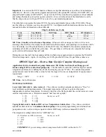
Chip Code Reference Table
Code
Stg. Enable
MU Time
ODT Mode
OT Function
HPDH
50°, 38°, 36°, 34°
90
HP
DT cal.
HPDF
50°, 38°, 36°, 34°
30
EL to SB
DT cal.
HPEL
50°, 38°, 36°, 34°
00
HP
DT cal.
MU Time - Standby or Gas Furnace Operation
- Whenever all four stages are full on (if it is not a
four-stage Electro-Mate, this simply means full Electro-Mate output), and operating at a continuous 100%
for a fixed delay (see Chip Code Reference Table, MU Time); the WarmFlo II controller automatically
terminates all electric and starts the gas furnace. The gas furnace will be used to complete the heating
cycle until room thermostat heat call ends.
During the next heat call, the heat pump and Electro-Mate stages again attempt to produce the WarmFlo
II desired temperature. Again, if everything is at 100% plus the MU time, the gas furnace takes over.
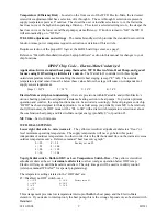
HPDH Chip Code – Electro-Mate Sized for Complete Heating Load
Application: 8-wire standard heat pump thermostat, WF II Electro-Mate, Heat Pump, gas/oil
furnace using ODT to control heat pump only
– The WarmFlo II controller with this chip has outside
temperature reference for enabling the electric heat staging (except “E” tab). The outside temperature
(actual sensor) must be below these values before the stage will come on, independent of supply sensor
requirement.
Stage 1 = 5Ø
°
F
2 = 38
°
F
3 = 36
°
F
4 = 34°F
MU Time
– Set to 90 minutes
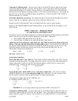
WF II DIAL SETTINGS
Lower right
dial switch
–
min. warm air
– The yellow screwdriver adjustment dial sets a “floor” or
level minimum operating temperature. The supply temperature will never go below this point
independent of outdoor temperature. In other words, this is the flat horizontal line on the warm air versus
outdoor temperature curve. Reference manual “heat loss curve graph”.
0 = 90
4 = 98
Factory set on #3.
1 = 92
5 = 100
2 = 94
6 = 102
3 = 96
7 = 104
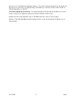
Top right dial switch - Built-in ODT or Low Temperature Switch-Over –
The yellow screwdriver
adjustment dial can be set to
terminate the heat pump
or via special programming can terminate heat
pump and electric to allow total gas operation below ODT temp. (reference manual WF-ANZ*).
The temperature settings related to the “ODT dial” are:
Ø = Disabled, no ODT switch-over
Factory set on #3.
1 = -15
°
F
5
=
10°F
2 = -10
°
F
6
=
20
°
F
3 = 0
°
F 7
=
30°F
4 = 5
°
F
COMMENT:
If you are using outdoor compressor built-in ODT, set the dial to “0”.
Содержание WARMFLO II
Страница 28: ......


