01/10/2008 17
HI321
2.
The terminal blocks for control wire hook-up are designed for a wire insertion and screw clamp
down. If there is no wire connected and the screw is loose, the screw may not necessarily make a
good electrical contact to the inside components. Example – if you are jumpering the thermostat
terminals without thermostat wire connection or if you are attempting to measure voltage on the
screw head, you may get erroneous or unpredictable results if the screw is not tightened down.
3.
Use general heating system logic information and basic understanding of the terminal block wiring
functions when measuring voltage to determine proper operation of this module.
4.
The outdoor sensor must be located outdoors for this controller to correctly operate. Do not leave the
outdoor sensor “hang in conditioned space” and attempt to run this system.
5.
Acquiring the WarmFlo II Analyzer test set or the PC software and serial port hook-up cable (see
previous page) is a positive tool for understanding and troubleshooting the WarmFlo II controller.
Either test set device can display all temperatures, real time evaluation of WarmFlo II functions,
provide temperature offsets for assimilating winter conditions, and reprogram the control chip
(program stays with the actual controller board).
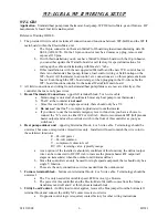
Bad sensor, safety
– if the internal logic detects open sensor wire, incorrectly wired sensor, or some bad
sensor transmitted value conditions; the green LED reverts to a pulsing mode. Basically the appropriate
sensor is set internally to a 0° value and the WarmFlo main board only allows stage 1 and stage 2 on.
-
OT sensor – approximately 1/10 second blip every ½ second
-
ST sensor – two, 1/10 second blips every ½ second
-
Both bad – ½ second on and ½ second off, alternating
Bad sensor, could disable cooling –
depending upon the ODT setting a bad sensor, even during cooling,
can affect the ODT of the compressor and the compressor will be off. Temporary fix is to set the ODT
dial to “0” position and get the sensor fixed. Verify with plug-in Analyzer and/or no blinking green LED.
Analyzer readout, sensor temperature constant 32° or 0°
– these two values represent digital bit
patterns that are hard to predict an error function. A blinking green light may or may not be experienced.
Typically the cable is too long, wrong type of sensor wire, or some electrical interference on the sensor
cable.
24-Volt Fuse –
the internal fuse is between the fan center “R” and all other WarmFlo II functions,
including the “R” going to the outdoor unit. Use only two amp, fast blow.
Содержание WARMFLO II
Страница 28: ......

