05/21/2009 11
BI501
EL MODE, amber – when illuminated the system is in the electric mode. If it is not illuminated
the utility load control receiver is in the interrupt or on-peak mode. If there is an optional or
remote standby switch, the status of the standby switch is also monitored by this amber LED.
HEAT ON, red – indicates a remote switch closure (t-stat or zoning end switch) is closed between
terminals R and W.
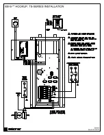
Inside Controller Board
STAGES, red – these four LED’s indicate which electric element stages are on and active.
Manual Reset, Hi-Limit
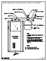
At the top of the vessel there will be either two or three surface mount hi-limits preset at 205° F. There is
no light indicator associated with these safety hi-limits. Also these 205° F safety limits break the L2
current carrying 240-volt wire going to the elements. Reset involves locating a small shiny lever or metal
tab protruding on the side of the black safety limit base. This small tab is pressed inward approximately
1/8” to “snap in” the contacts.
Safety caution
– the wires and screws have 240-volt potential and can be dangerous. Turn off
circuit breakers before investigating or attempting to reset the 205° F safety limits.
Internal Fuse
The fuse on the controller board protects the transformer secondary, external items connected to “R”, and
the circuit board itself. Replace with 2-amp fast blow, AGC2 or equivalent.
Stat Heat Anticipator
- If it is a mechanical stat, verify heat anticipator has been set at Ø.2 (non-zone
system).
System Pressure
The side press/temp. gauge should be at approximately 10 to 16 PSI at room temperature water and
should not rise more than approximately 4 PSI at the operating or hot water temperature. If the pressure
change is more than approximately 4 PSI, the expansion tank is too small or there is a problem with the
expansion tank piping, expansion tank itself.
Cold slab, outdoor reset and temperature sensing prevent full boiler on
– by adding a
temporary
jumper between the lower W screw terminal and the upper left “E” tab, all temperature sensing functions
are bypassed and the control board will step in all the stages.
Caution:
This jumper shall not be a
permanent function, jumper needs to be removed after slab is approaching normal temperature.
REPLACEMENT PARTS
WFSB
Outlet sensor, 3 ft.
EB5623S
Controller, temp. sensing
UFUSE0440
2-amp fuse, fast blow (AGC2)
5127 Heating
relay
5535
Safety hi-limit, manual, 205°
5537
First hi-limit, auto-reset, 180°
5453
Relief valve, 30 PSIG
5456A Gauge
press/temp.
5640
GE 60A circuit breaker
5639
GE 30A circuit breaker
5652
Square D 60A circuit breaker
5650
Square D 30A circuit breaker
EB5520
Electric element, 240, 4.5 kW
5541
Transformer, 24V, 40VA


