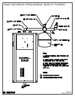
Electro Industries EB-S-13 Скачать руководство пользователя страница 12

05/21/2009 10 

BI501 

CONTROLLER SETUP 


Temperature set point

 – the front red “knob” allows for field or user setting of the outlet water 

temperature.  The built-in sensor and controller will attempt to regulate the electric element stages around 
this set temperature.  The smallest staging increment is 4.5 kW; therefore, there will some fluctuation 
around this set point.  Field setting the outlet temperature at the design or realistic temperature required 
by the radiation is more efficient. 


The front panel allows selection of the operating temperature.  The table below should coincide with the 
decal on the front panel. 


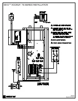
Circulator pump mode

 – as factory set, the circulator pump is controlled directly from the “W” input 

terminal.  In this setup the circulator pump continues during load control interrupt (or optional remote 
standby switch).  There is a provision within the controller board (inside) to allow the circulator pump to 
not operate during load control interrupt. 


On the inside control board, just above the two bottom 
terminal blocks, is a small pin jumper arrangement.  The 
black “device” sets up the pump mode.  Just below this pin 
jumper arrangement are W and L lettering.  When the two 
pin shorting device is in the W position, the pump is a 
direct function of R to W input.  When the two pin jumper 
is in the L position, the pump is interrupted during a load 
control. 


WARNING: 

This shorting device must be in one of the two positions for the circulator pump to properly 

operate. 


OPERATIONAL TIPS 


Heating Cycle 

1.


External R to W contact closure. 

2.


Assume the load control receiver device (or remote option standby switch) is in the off-peak or 
non-interrupt mode.  This is verified by the front panel amber LED being illuminated. 

3.


Circulator pump starts. 

4.


30-second plus delay before staging lights or element relays close.  This delay allows the pump to 
circulate the system water past the outlet water temperature sensor and allows the controller logic 
to determine how many elements to energize.  If the water temperature is greater than the set 
point, elements will not come on. 


Monitor Lights, Front Panel


HI-LIMIT, red – this will 

only

 illuminate when the vessel hi-limit opens due to excessive high 

water temperature.  This hi-limit is self resetting. 


PWR ON, green – basically this is illuminated at all times.  It represents 24-volt power source, 
good fuse, controller logic is operational, and a good outlet sensor.  If the outlet sensor is 
inoperative, incorrectly wired, or malfunctioning; this green monitor LED will be in the blinking 
or pulsing mode (see page 11). 

Содержание EB-S-13

Страница 1: ...acity and flow changes may cause some internal timing overtemp conditions With the mixture of zones the zone controller ZTS option is highly recommended see page 2 This series is equipped for load management interrupt and can apply to standard baseboard radiation dual heat combinations under floor radiant wood boiler supplement etc ACCESSORIES Attached BL001 lists various accessory or option items...

Страница 2: ...Feature 4 Boiler Plumbing Kit Placement 4 Installation Requirements 4 Mechanical Installation Under Floor Radiant 6 Dual Heat 7 Electrical Hookup 8 Water Fill Procedure 9 Controller Setup 10 Operational Tips 10 Replacement Parts List 11 Troubleshooting Repair Helps 12 Sequence 12 Drawings Basic Mechanical BX501 Piping Install Kits BX502 Hookup BH501 Internal Wiring Schematic BS501 Boiler Accessori...

Страница 3: ...ed as hot boiler This will defeat the Electro Boiler Rewire as required standby boiler is turned on from the brown wires In the case of existing fossil fuel boiler conversions it is assumed the expansion tank valving air bleeder and circulation pump are in place in good operating condition and adequate for the overall system design In the case of new installation radiant floor or baseboard use sta...

Страница 4: ...the boiler is turned on via contact closure on R and W At least one zone must be open before turning on the primary pump Electro Boiler Do not design a system where the Electro Boiler is supposed to operate as a hot boiler based upon its outlet sensor without the primary pump circulating water minimum 2 GPM is required New improved feature the EB ZTS 1 zone controller priority zone now has the abi...

Страница 5: ...oil etc heat only wall t stat connected to operate zone valves see previous section or for single zone the t stat is connected directly to Electro Boiler R and W Floor radiant comfort and proper space heating response is a direct relationship to the thermostat type and the placement of the thermostat sensing bulb Typically an under floor heating system can be broken down into three categories A En...

Страница 6: ...k must be performed by trained qualified contractors or technicians Electro Industries Inc sponsors installation and service schools to assist the installer Visit our web site at electromn com for upcoming service schools WARNING ALL ELECTRICAL WIRING MUST BE IN ACCORDANCE WITH NATIONAL ELECTRIC CODE AND LOCAL ELECTRIC CODES ORDINANCES AND REGULATIONS WARNING OBSERVE ELECTRIC POLARITY AND WIRING C...

Страница 7: ...staller must know this product well enough to instruct the end user on its safe use Safety is a matter of common sense a matter of thinking before acting Professional installers have training and experienced practices for handling electrical sheet metal and material handling processes Use them CLEARANCES MINIMUM CLEARANCE FROM COMBUSTIBLE SURFACES SUGGESTED MINIMUM SERVICE CLEARANCE BACK 0 INCH 0 ...

Страница 8: ...agm tank as provided in the plumbing kit or a basic empty tank where air is compressed at the tank top Inlet Temperature Gauge recommended to observe the operation of the system Air Vent install with the pressure relief valve as shown on drawing BX502 page 2 or part of the air eliminator shown on BX502 page 3 Inline Air separator this can be installed ahead of the pump with the expansion tank move...

Страница 9: ...T ports must be at the top The unit will not function properly with the vessel in a horizontal position NOTE Mount at least 20 inches above the floor to allow element removal and service at the bottom 5 Typically this unit is wall hung next to the existing boiler 6 Use the pipe fittings to install the safety relief valve and air vent Add the necessary piping to the safety relief valve so that wate...

Страница 10: ...e system pump controlled by these two terminal screws 4 Operating Thermostat two types can be used Connection is at the control board bottom Standard Mechanical connect to R and W bottom right Set thermostat internal heat anticipator to 0 2 Electro Stat ES 24 C RS or ES 24 SRO 3 wire connection required R to R W to W C to common The Electro Stat remote sensor can be extended as required This is a ...

Страница 11: ... user needs to make sure the pressure within the boiler loop does not exceed 30 PSI Careful control of the supply water ball valve opening can take care of this Also at steps 6 and 10 use caution to make sure the building water supply pressure does not spike the system 1 Connect the temporary household water supply source probably hose connection to the water supply connection input NOTE If water ...

Страница 12: ... the two pin shorting device is in the W position the pump is a direct function of R to W input When the two pin jumper is in the L position the pump is interrupted during a load control WARNING This shorting device must be in one of the two positions for the circulator pump to properly operate OPERATIONAL TIPS Heating Cycle 1 External R to W contact closure 2 Assume the load control receiver devi...

Страница 13: ...s the transformer secondary external items connected to R and the circuit board itself Replace with 2 amp fast blow AGC2 or equivalent Stat Heat Anticipator If it is a mechanical stat verify heat anticipator has been set at Ø 2 non zone system System Pressure The side press temp gauge should be at approximately 10 to 16 PSI at room temperature water and should not rise more than approximately 4 PS...

Страница 14: ...nside control board left side contains a E tab which can be used to directly step in the heating stages and in essence bypass the temperature sensing and control functions The E tab has the highest priority and overrides all temperature sensor functions In other words when jumpering from W to E all four stages are hard on Note Verify pump is operating prior to using the E terminal Since activating...

Страница 15: ......

Страница 16: ......

Страница 17: ......

Страница 18: ......

Страница 19: ...1 J5 SB 4 3 2 STG STG STG STG 1 SW5 CALIB SENSOR TB1 J4 TEMP TEMP SENSOR RED ST OT COM BLUE BLUE LMC T STAT CABLE TB2 W TB2 R TB2 C 5 NO COM 4 PUMP 2 3 L1 L2 240VAC SOURCE POWER CIRCUIT BREAKER L1 2 120VAC CIRCUIT BREAKER NEUTRAL TB2 R TB2 C TB2 W L1 L2 L2 L1 L2 L1 5 COMMON REQUIRED FOR ELECTRO STAT RELAY CONTACT FOR PUMP 4 DRAWING SHOWN WITH OPTIONAL SINGLE FEED BUS APPLIED MUST ORDER SEPARATELY ...

Страница 20: ......

Страница 21: ...tem for Brand X boilers or dual EB R L E Series EB ZC 4 wiring and convenience interface isolated boiler end switch EB 5415A low cost 2 or 3 zones sheds one boiler stage Mini Boiler enhancement ZONE CONTROLLER SLAB STAT Sensing and controlling the system based upon radiant floor surface temperature or the concrete mass has very positive benefits Radiant floor air stat in the same area as a forced air...

Страница 22: ...es boilers come standard equipped with outlet temperature pressure gauge pressure relief safety valve and when applicable the WarmFloTM electronic control sensors These kits provide the additional components for easy installation 5585 Mini Boiler 10 kW TS Series 5586 TS Series Standard 5578 3 4 Pipe 5582 1 Pipe 5579 1 1 4 Pipe 120V 1 25 HP maintenance free wet rotor circulator Pump curve example 5...

Страница 23: ...ade by Electro Industries or its authorized representative Electro Industries will cover reasonable labor costs to repair defective product or product parts for ninety 90 days after installation TWENTY YEAR 20 LIMITED WARRANTY ON BOILER ELEMENTS AND VESSELS Electro Industries Inc warrants that the boiler elements and vessels of its products are free from defects in materials and workmanship throug...

Страница 24: ...ill be null and void 4 The purchaser shall have maintained the product in accordance with the manual that accompanies the unit Annually a qualified and licensed contractor must inspect the product to assure it is in proper working condition 5 All related heating components must be maintained in good operating condition 6 All lines must be checked to confirm that all condensation drains properly fr...

Отзывы: