


User Manual of Network Video Recorder
58
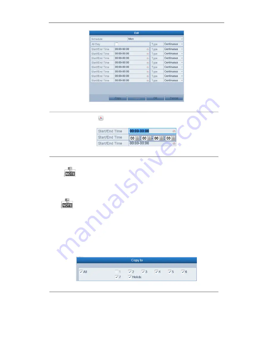
Figure 5. 7
Recording Schedule Interface
You can click the
button to set the accurate time of the schedule.
II.
To schedule an all-day recording, check the checkbox after the
All Day
item.
Figure 5. 8
Edit Schedule
III.
To arrange other schedule, leave the
All Day
checkbox blank and set the Start/End time.
Up to 8 periods can be configured for each day. And the time periods can’t be overlapped each
other.
IV.
Select the record type in the dropdown list.
To enable Motion, Alarm, M | A (motion or alarm), M & A (motion and alarm) and VCA (Video
Content Analysis) triggered recording and capture, you must configure the motion detection settings,
alarm input settings or VCA settings as well. For detailed information, refer to
Chapter 8.1
,
Chapter
8.2 and Chapter 8.5
.
The VCA settings are only available to the smart IP cameras.
Repeat the above edit schedule steps to schedule recording or capture for other days in the week. If the
schedule can also be applied to other days, click
Copy
.
Figure 5. 9
Copy Schedule to Other Days
V.
Click
OK
to save setting and back to upper level menu.
VI.
Click
Apply
in the Record Schedule interface to save the settings.
Draw the schedule:
I.
Click on the color icons, you can choose the schedule type as continuous or event.
Содержание EI-6120 NIP-16
Страница 1: ...Network Video Recorder User Manual...
Страница 28: ...User Manual of Network Video Recorder 27 12 Click OK to complete the startup Setup Wizard...
Страница 41: ...User Manual of Network Video Recorder 40 Figure 3 6 Information...
Страница 112: ...User Manual of Network Video Recorder 111 Figure 7 40 Synchronizing...
Страница 117: ...User Manual of Network Video Recorder 116 to copy the settings to them Figure 8 8 Copy Settings of Alarm Input...
Страница 119: ...User Manual of Network Video Recorder 118 5 Click the OK button to complete the video loss settings of the channel...
Страница 163: ...User Manual of Network Video Recorder 162 Figure 10 23 View HDD Status 2...
Страница 198: ...User Manual of Network Video Recorder 197...


