7
ASSEMBLY INSTRUCTIONS
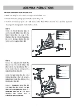
STEP 1:
Attach the
Front Stabilizer (No. 8)
and the
Rear Stabilizer (No. 2)
to the
Main Frame (No. 1)
using 4
Flat
Washers (No. 5)
, 4
Domed Nuts (No.
6)
and 4
Carriage Bolts (No. 3)
.
Tighten with
a
Spanner (No. 90)
.
STEP 2:
Release the
Adjustment Knob (No.
10)
and insert the
Vertical Seat Post
(No. 12)
into the
Main Frame (No. 1)
.
Set at desired height and tighten the
Adjustment Knob (No. 10)
.
Attach the
Seat Slider (No. 15)
to the
Vertical Seat Post (No. 12)
using the
Adjustment Knob (No. 86)
and the
Flat Washer (No. 85)
.
Loosen 2
Hexagonal
Nuts
(No. 87)
from
Seat (No. 16)
. Attach the
Seat
(No. 16)
to
Seat Slider (No. 15)
with 2
Hexagonal
Nuts
(No. 87)
that were
loosened then tighten with a
Crosshead Spanner (No. 89)
.
1. PREPARATION BEFORE STARTING ASSEMBLY:
A. Make sure that you have adequate workspace around the item.
B. Use the hardware package provided when assembling unit.
C. Confirm all necessary parts and tools are available (Note:
This instruction
sheet
provides exploded
drawing with all single parts marked with numbers).
Содержание IC033
Страница 2: ......
Страница 4: ...3 EXPLODED DRAWING...
Страница 18: ...17...
Страница 19: ...18...
Страница 20: ...19...


