manualshive.com logo in svg
background image

“Hooked on Quality”

P A R T S   A N D   O P E R A T I O N   M A N U A L

HOIST SERIAL NUMBER

MODEL

SL-

1

05

Содержание swaploader SL-105

Страница 1: ... Hooked on Quality PA R T S A N D O P E R AT I O N M A N U A L HOIST SERIAL NUMBER MODEL SL 105 ...

Страница 2: ......

Страница 3: ...mper Assembly 2 17 Bumper Assembly w Extension 2 19 Fender Assembly 2 21 Light Bar Assembly 2 23 Roller Roller Mount Assembly 2 27 Toolbox Assembly 2 29 III OPERATION Loading a Container 3 1 Dumping a Container 3 2 Placing a Container on the Ground 3 3 IV MAINTENANCE Maintenance Instructions 4 1 Lubrication Diagram 4 2 Hydraulic Oil Specifications 4 3 Hydraulic Filter Specifications 4 3 Mast Lock ...

Страница 4: ...nk Circuit 5 9 Pump Circuit 5 10 Manual Controls 2 Section 5 11 V OPTIONS Cylinder Circuit BL 105 EHV 6 1 Cylinder Circuit BL 105 STD 6 2 U Lock Assembly 6 3 Manual Controls 3 Section 6 4 Hoist Installation Kit EHV 6 5 Tank Circuit EHV 6 6 Tank Circuit 3 Section 105 6 7 Pump Circuit EHV 6 8 Hose Circuit EHV 6 9 Hose Circuit 3 Section EHV 6 10 ...

Страница 5: ...ty of personal injury or machine damage Record your SwapLoader Hoist serial number in the appropriate space provided on the title page Your SwapLoader dealer needs this information to give prompt efficient service when ordering parts It pays to rely on an authorized SwapLoader Distributor for your service needs For the location of the Distributor nearest you contact SwapLoader NOTE It is SwapLoade...

Страница 6: ...ts furnished by SwapLoader U S A Ltd SwapLoader will invoice the distributor or authorized service center for the replacement parts and freight Upon completion of the repair any defective parts to be returned for warranty consideration must be returned freight prepaid with a copy of the SwapLoader issued RGA form and a copy of the completed warranty claim report form Upon evaluation of the returne...

Страница 7: ...ion or with the hook to the rear 4 Do not exceed 1 500 Engine RPM when operating the Power Take Off P T O Never leave the P T O in gear while transporting 5 The hoist must be used with containers that properly fit the hook and rear hold downs The container specifications must match the hoist specifications 6 Keep the containers and hoist in good working order DO NOT use if repairs are needed Perfo...

Страница 8: ... It is the responsibility of the owner and or installer to ensure that any additional safety devices required by state or local codes are installed on the SwapLoader Hoist and or Truck Chassis 10 Keep away from overhead power lines Serious injury or death can result from contact with electrical lines Use care when operating hoist near electrical lines to avoid contact 11 Avoid contact with high pr...

Страница 9: ...DY SPECIFICATIONS 3 ONE 90P09 HYDRAULIC OIL SPECIFICATIONS 4 ONE 90P10 HYDRAULIC OIL FLAMMABLE 5 2 90P11 HOIST FALLING 6 ONE 90P12 LEVER CONTROL 7 ONE 90P13 SAFETY INSTRUCTIONS 8 2 90P14 SWAPLOADER JIB 9 ONE 90P18 RELIEF VALVE 10 ONE 90P78 HIGH PRESSURE FLUID 11 4 90P96 SL 105 DECAL 12 2 91P06 LUBRICATION POINTS 1 5 ...

Страница 10: ...the SwapLoader Safety Decals and their part numbers Please use when reordering replacement decals 90P07 OPERATIONS SERVICE MANUAL 90P08 HOIST BODY SPECIFICATIONS 90P09 HYDRAULIC OIL SPECIFICATIONS 90P10 HYDRAULIC OIL FLAMMABLE 90P11 HOIST FALLING 90P12 LEVER CONTROL 1 6 ...

Страница 11: ...Section I Introduction 1 0 INT SL 105 90P13 SWAPLOADER SAFETY INSTRUCTIONS 90P14 SWAPLOADER JIB 90P18 RELIEF VALVE 90P78 HIGH PRESSURE FLUID 90P96 SL 105 91P06 LUBRICATION POINTS 1 7 ...

Страница 12: ...g is located at the front driver side of the hoist gray arrow on first picture The Serial Number is stamped into the frame of the hoist on the top of the inner rail shown at the rear of the hoist black arrow on first picture An example of a 6 character serial number is shown in the second picture 1 8 ...

Страница 13: ...E The installation of the SwapLoader on a truck chassis will generally follow these steps 1 Install hoist assembly onto truck chassis 2 Mount the hydraulic control valve or EHV system to the hoist and install the hydraulic plumbing from the control valve to the hydraulic cylinders Then install the control levers in the cab and route the control cables to the hydraulic control value assembly 3 Inst...

Страница 14: ...a truck with a long CA check that the hoist and the light kit are positioned far enough back to eliminate any interference between the fender and the light kit You should also consider the final weight distribution regarding the bridge codes and axle GVWR when positioning the hoist NOTE THE ABOVE SPECIFICATIONS ARE A MINIMUM REQUIREMENT IT IS THE RESPONSIBILITY OF THE OWNER OPERATOR TO ENSURE THE ...

Страница 15: ...uck chassis with the 1 2 diameter bolts washers and locking hex nuts provided Torque to 110 ft lb 3 Weld the mount brackets to the hoist main frame as indicated on Fig C and Fig D You may need to modify the mount brackets or add shim plates to allow for variances in the width of the truck chassis as well as to allow for top rivets stepped channels etc NOTE PRIOR TO ANY WELDING CONSULT THE TRUCK MA...

Страница 16: ...rs 5 Assemble and install the control lever console see Fig E Typically the console is fastened to the floor of the cab and the control cables are routed through additional holes drilled in the floor Your installation may require that additional brackets be fabricated or other modifications made 6 Attach the control cables to the control levers and route the cable through the holes in the cab Inst...

Страница 17: ...nd flange onto sleeve and turn flange adaptor flange sleeve assembly entire length of threaded hub back over the cable 2 Turn 250 28 UNF jam nut onto cable threaded rod until it bottoms 3 Place clevis of threaded rod and bottom against jam nut Turn other 250 28 UNF jam nut onto threaded rod until it bottoms against clevis Align clevis so it will mate with spool terminal eye and secure jam nut agai...

Страница 18: ...een engaged or disengaged 1 Review all directions and diagrams provided before starting installation 2 Mount valve to the hoist s Main Frame and attach all hoses hose clamp assemblies and fittings as shown on Pg 6 7 3 Mount Indicator Light Box in the truck cab where it will be clearly visible to the operator 4 Route Indicator Light and Harness Pt No 40P60 from the truck cab to the U Lock cylinder ...

Страница 19: ...hown on Pg 6 9 also see Illustrations Electric Over Hyd Valve SERVICE PARTS SL 105 ITEM PART QTY DESCRIPTION 1 13P24 2 Hose Assy 39 08 08FJ 08FJ90 2 13P76 2 Hose Assy 52 08 08FJ 08FJ45 3 22P82 1 Solenoid Operated Valve Coil 4 22P83 1 Solenoid Operated Valve Spool 5 22P84 1 Relief Valve Cartridge 3250 6 22P85 1 Dump Valve NOTE THE FIGURES BELOW DO NOT NECESSARILY DEPICT YOUR HOIST AND ARE ONLY MEAN...

Страница 20: ...the truck cab Determine the best location in the cab for the control box location and install with mounting screws included The location should be such that the controls can be easily reached while operating the truck 4 Hardwire or plug in provided 12V adapter for control box 2 8 ...

Страница 21: ...ns Electric Over Hyd Valve SERVICE PARTS SL 105 ITEM PART QTY DESCRIPTION 1 13P24 2 Hose Assy 39 08 08FJ 08FJ90 2 13P28 1 Hose Assy 57 08 08FJ 08FJ45 3 13P32 1 Hose Assy 58 08 08FJ 08FJ45 4 13P76 2 Hose Assy 52 08 08FJ 08FJ45 5 22P82 1 Solenoid Operated Valve Motor 6 22P83 2 Solenoid Operated Valve Cylinder 7 22P84 1 Relief Valve Cartridge 3250 8 22P85 1 Dump Valve NOTE THE FIGURES BELOW DO NOT NE...

Страница 22: ...in the cab for the control box location and install with mounting screws included The location should be such that the controls Pt No 22P95 can be easily reached while operating the truck 4 Route indicator light harness from control box to the U Lock Cylinder 5 Hardwire or plug in provided 12V adapter for control box 2 10 ...

Страница 23: ... the bushing style pumps are single rotation rotation specific All SwapLoader hooklift hoists come standard with a CCW left hand rotation pump which will work for most manual transmission applications For most automatic transmission applications a CW right hand rotation pump is needed call SwapLoader for price and availability NOTE CONSULT THE PTO SUPPLIER WHENEVER UNCERTAIN ABOUT THE CORRECT PUMP...

Страница 24: ...P T O Bolts are not provided 2 Install the hydraulic fittings into ports on the hydraulic pump as shown on Pg 5 10 3 Connect the suction hose assembly to the hydraulic tank 1 I D hose and route to the hydraulic pump in as short and straight line as possible Be sure to route the hose clear of exhaust components and of the drive shaft Extra hose is provided so the hose can be shortened to an appropr...

Страница 25: ...1 Select a location to mount the hydraulic tank Reference Fig G or Pg 5 11 for the suggested location of the hydraulic tank to the rear of the control valve assembly on the left hand side of the truck The hydraulic hoses have been sized for the tank to be mounted in this general area The tank can be located on the right hand side or behind the cab if necessary which means longer hoses may be requi...

Страница 26: ...of the control levers corresponds to the movement of the cylinders per the figure below 6 Install all safety decals and product decals per as shown on Pg 1 5 after final installation and painting have been completed 7 Fill out the Product Registration form online at https www swaploader com warranty registration CAUTION The SwapLoader hoist must be used with bodies or containers that properly fit ...

Страница 27: ...IS DRAWING PROVIDES THE CRITICAL SUB FRAME DIMENSIONS FOR COMPATABILITY WITH THE SWAPLOADER HOOK LIFT HOIST IT IS THE SUB FRAME SUPPLIER S RESPONSIBILITY TO PROVIDE A SUB FRAME OF SUFFICIENT CAPACITY WHICH PROPERLY SUPPORTS THE BODY CONTAINER WHEN USED WITH THE HOOK LIFT HOIST 4 SWAPLOADER MANUFACTURED 100 SERIES A FRAMES REQUIRE A 5 INCH LONGSILL HEIGHT 100 SERIES SUB FRAME DIMENSIONS HOIST COMPA...

Страница 28: ...This Page Intentionally Left Blank ...

Страница 29: ...ce of Motor Carrier Safety OMCS regulations Regulation 393 86 requires that no bumper be located more than 30 off the ground when the truck is empty and the end of the bumper should not be located more than 24 from the extreme rear of the vehicle including truck bodies see Fig B Once the length has been determined for the vertical channels weld them to the bottom of the truck frame see additional ...

Страница 30: ...SCONNECTED AND THE GROUND LEAD FROM THE WELDER SHOULD BE AS CLOSE TO THE PART BEING WELDED TO AVOID THE POSSIBILITY OF ARCING ACROSS BEARINGS GEARS ETC 2 ALL WELDS SHOULD BE DONE UTILIZING A LOW HYDROGEN WELDING PROCESS BUMPER LOCATION CHART DIM A DIMENSION B MAX SL 105 SL 145 SL 160 SL 212 SL 214 SL 220 SL 222 SL 240 SL 2418 SL 330 SL 400 SL 412 SL 406 SL 518 SL 520 SL 650 24 5 8 13 1 2 15 3 4 15...

Страница 31: ... Carrier Safety OMCS regulations Regulation 393 86 requires that no bumper be located more than 30 off the ground when the truck is empty and the end of the bumper should not be located more than 24 from the extreme rear of the vehicle including truck bodies see Fig B Once the length has been determined for the vertical channels weld them to the truck frame see additional notes on the next page 4 ...

Страница 32: ... THE WELDER SHOULD BE AS CLOSE TO THE PART BEING WELDED TO AVOID THE POSSIBILITY OF ARCING ACROSS BEARINGS GEARS ETC 2 ALL WELDS SHOULD BE DONE UTILIZING A LOW HYDROGEN WELDING PROCESS BUMPER LOCATION CHART DIM A DIMENSION B MAX SL 105 SL 145 SL 160 SL 212 SL 214 SL 220 SL 222 SL 240 SL 2418 SL 330 SL 400 SL 412 SL 406 SL 518 SL 520 SL 650 24 5 8 1 3 4 22 1 2 21 3 4 25 1 4 21 3 4 21 1 2 21 24 1 4 ...

Страница 33: ...r truck chassis 4 Mark mounting holes through the fender bracket weldment onto the fender Remove the bracket and drill Ø7 16 holes in fender see Fig C 5 Attach fender bracket weldments to ender using fasteners provided 6 Weld mounting plates Pt No 21H37 to fender tubes Pt No 21H61 7 Position fender tubes with mount plates on hoist main frame align with fender bracket weldments NOTE Fender tube len...

Страница 34: ... 2 HHCS 0 07 9 01P21 16 3 8 16 UNC x 2 1 2 HHCS 0 09 10 90P24 2 Fender Aluminum 19 00 10 90P25 2 Fender Steel 35 00 Note Will include either 2 90P24 aluminum fender or 2 90P25 steel fender depending on order Installation is the same for both aluminum and steel fender NOTE 1 PRIOR TO ANY WELDING CONSULT THE TRUCK MANUFACTURE FOR ANY SPECIAL PRECAUTIONS THAT MAY NEED TO BE TAKEN TYPICALLY THE BATTER...

Страница 35: ... interference Drill mounting holes as required and mount using fasteners provided See Fig C 5 Attach the taillight module to the stub light bar weldments with the fasteners provided see Fig C 6 Mount the identification light bar at top center of the center plate Pt No 63H08 using the fasteners provided see Fig C 7 Mount license lamp right of the license plate See Fig B using the fasteners provided...

Страница 36: ...ate 27 33 3 00P44 6 3 8 16 x 1 1 2 HHCS 0 07 4 00P34 6 3 8 16 Locking Hex Nut 0 02 5 00771 6 Ø3 8 Flat Washer 0 01 6 01P18 4 5 8 11 x 3 HHCS 0 35 7 00P81 8 8 32 x 1 RHMS 8 00P82 8 8 32 Hex Nut 9 00P83 8 8 Lock Washer 10 40P32 1 Lic Light Assy w o Harness 11 40P34 REF License Lamp Harness 12 40P35 REF Id Light Bar Rail 13 40P37 REF Id Light Bar Harness 14 40P38 REF Junction Box Assembly 15 40P39 RE...

Страница 37: ...Section II Installation Accessories 2 8 INS ACC LEDLB 2 25 ...

Страница 38: ...This Page Intentionally Left Blank ...

Страница 39: ...nd as wide as possible for stability For hoist and folding bumper clearance do not place brackets any closer than 11 to the subframe longsill see Fig A Also the roller axle center line should be approximately 1 11 16 below the bottom of the subframe longsill for roller clearance see Fig A 3 Some modification to the roller mount bracket may be required for the roller mount to fit properly If the ex...

Страница 40: ...h the roller axle Pt No 10H31 and the fasteners provided see Fig C Grease the rollers before use 10H91 10H90 Figure B Figure C MATERIAL LIST FOR 10H90 AND 10H91 ITEM PART QTY DESCRIPTION WT lb ea 1 32H03 4 Roller Ear 11 95 2 10H12 2 Roller Wdmt 39 76 3 10H31 2 Roller Axle Wdmt 7 28 4 00P62 2 3 8 16 UNC x 1 Bolt 05 5 90P03 2 1 8 NPT Grease Zerk 01 6 00755 2 3 8 Dia Lock Washer 01 7 00P36 2 3 8 Dia ...

Страница 41: ...forward bottom edge 6 Mark position of mounting holes through brackets onto toolbox Remove toolbox and drill 9 16 dia holes 7 Mount toolbox to brackets using fasteners provided see Fig A MATERIAL LIST FOR 10H92 OR 11H12 ITEM PART QTY DESCRIPTION WT lb ea 1 10H88 2 18 Toolbox Bracket 11 34 2 22H71 2 Toolbox Rubber Spacer 27 3 90P27 1 Aluminum Toolbox 50 00 3 90P37 1 Steel Toolbox 72 00 4 00784 8 1 ...

Страница 42: ...This Page Intentionally Left Blank ...

Страница 43: ...TROL LEVER BACKWARD THEN TILT THE ARM BACKWARD LEFT CONTROL LEVER BACKWARD STEP 3 MAKE SURE THE WORK AREA IN FRONT OF THE CONTAINER IS CLEAR OF PEOPLE AND OBSTACLES MOVE THE TRUCK BACKWARDS UNTIL THE HOOK ENGAGES THE CURVED LIFTING BAR OF THE CONTAINER NEVER EXTEND THE JIB TO REACH THE PROPER CATCHING HEIGHT RATHER TILT THE ARM WARNING MAKE SURE WORK AREA IS CLEAR OF PEOPLE AND OBSTACLES PRIOR TO ...

Страница 44: ...RING LIFTING STEP 5 WHEN THE CONTAINER IS RESTING ON THE FRAME MOVE THE JIB FORWARD ALL THE WAY TO ENSURE THE CONTAINER IS HELD IN THE BODY LOCKS RIGHT CONTROL LEVER FORWARD DISENGAGE THE P T O LOCK U LOCK IF INSTALLED ON HOIST DUMPING STEP 1 MOVE THE JIB FORWARD RIGHT CONTROL FORWARD TO ENSURE THAT THE CONTAINER IS LOCKED STEP 2 EXTEND THE MAIN LIFT CYLINDERS LEFT CONTROL BACKWARD CAUTION DO NOT ...

Страница 45: ...NER TOUCHES THE GROUND RELEASE THE BRAKES TO FREE THE TRUCK FOR FORWARD MOVEMENT CAUSED BY THE CONTAINER STEP 3 ROTATE JIB ALL THE WAY BACK UNTIL THE CONTAINER TOUCHES THE GROUND PULL AWAY FROM CONTAINER AND ROTATE JIB BACK INTO THE TRANSPORT POSITION WARNING 1 DON T OVER SPEED THE PUMP 1 500 RPM MAXIMUM 2 DON T DUMP MOUNT OR DISMOUNT BODIES ON UNEVEN GROUND 3 DON T DRIVE WITH THE HOIST IN THE DUM...

Страница 46: ...This Page Intentionally Left Blank ...

Страница 47: ...er to lubrication diagram Fittings on lift cylinders quantity 4 Front pins on rear pivot joint weldment quantity 2 Fittings on rear pivot pins and rollers quantity 4 2 Check all bolts and retighten as required 3 Check adjustments on mast lock safety latch mechanism Refer to the Mast Lock Inspection Adjustment Instructions on Pg 4 4 of the Maintenance section 4 Check adjustments on the jib lockout ...

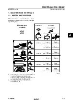
Страница 48: ...Section IV Maintenance 4 0 MAI SL 105 LUBRICATION DIAGRAM LEGEND GW Grease Weekly GM Grease Monthly 4 2 ...

Страница 49: ...on Nominal Flow Rating 25 GPM NOTE 1 ALWAYS CONSULT YOUR LOCAL HYDRAULIC OIL SUPPLIER FOR MORE INFORMATION 2 USE CAUTION WHEN OPERATING AT OR BEYOND THE RECOMMENDED TEMPERATURE EXTREMES 3 DO NOT OPERATE THE HOOKLIFT HOIST WHEN HYDRAULIC OIL TEMPERATURE ON TANK GAUGE EXCEEDS 160 F 71 C AS DAMAGE TO HYDRAULIC COMPONENTS CAN OCCUR ISO Grade 32 Company Name Brand Name Grade Castrol BP Paradene 32AW CI...

Страница 50: ...t approximately a 1 4 see illustrations below INSPECTION The mast lock assembly comes adjusted from the factory and should provide years of trouble free operation however there may come a time when an adjustment may be required Prior to making any adjustments SwapLoader recommends that you begin with inspecting all mast lock components for damage or wear see illustration below Inspect the adjustme...

Страница 51: ... the telescopic jib may experience a reduction in extension or retraction speed to the point of stalling out INSPECTION When a noticeable loss in extension or retraction speed of the telescopic jib is experienced the first step should be to inspect the jib lockout valve and valve mount ramp to ensure that they are adjusted properly and in good working order The jib lockout valve is located on the ...

Страница 52: ...ith respect to the valve ramp by turning the adjustment screw on the valve mount bracket as follows Clockwise Adjustment Moves the jib lockout valve closer to the valve ramp Counter Clockwise Adjustment Moves the jib lockout valve away from the valve ramp Once the valve has been moved back into proper adjustment then tighten up the mount bracket screws PART NUMBER SPECIFICATION SwapLoader Pt No Wo...

Страница 53: ...ed with a female JIC 4 hydraulic adapter preferably located at the end of a 3 8 inch diameter high pressure hydraulic hose that is 2 to 3 foot in length see illustration below Should you not be able to source a hydraulic gauge locally SwapLoader can provide one at a reasonable cost Hyd Pressure Gauge Hose Assembly Pt No 22P10 PRESSURE CHECK STEPS 1 Locate the 90 male JIC 4 hydraulic adapter SWL 10...

Страница 54: ...he truck and engage the P T O 4 Push the lift dump circuit lever forward until the lift dump cylinders bottom out see illustration below Continue to push the lever forward until steps 5 6 are complete 5 Check the gauge for the maximum developed system pressure The SL 105 should have a reading of 3 250 PSI 6 With the pressure check complete release all functions and disengage the P T O 4 8 ...

Страница 55: ...the pressure gauge to the hydraulic control valve see illustration below 3 Start the truck 4 Push the lift dump circuit lever left until the lift dump cylinder bottoms out see illustration on the right Continue to push the lever forward until steps 5 6 are complete 5 Check the gauge for the maximum developed system pressure The SL 105 should have a reading of 3 250 PSI 6 With the pressure check co...

Страница 56: ...05 hooklift the gap between the top of the jib horizontal tube and the top inside surface of the outer tube should be kept between 1 16 to 1 8 see Section View A A below When a gap greater than 1 8 exists since the clamp assembly has a fixed elevation inspect the clamp liner clamp plate and fasteners for excessive wear or damage see Section View A A below Replace parts as needed to bring the outer...

Страница 57: ...r adjustment bolt 2 Tighten the adjustment nuts equally so that the clamp bar is drawn up evenly Be sure to keep the jib horizontal tube level make sure the gap is even between the inner and outer tubes from left to right 3 Once the gap between the top of the jib horizontal tube and the top inside surface of the outer tube is between 1 16 to 1 8 the jam nuts can be tightened up 4 11 ...

Страница 58: ...atively the figure above is labeled showing which spool performs which function Press the button on the spool hold and then press the manual over ride button on the bottom of the valve shown in the figure to the right NOTE 2 A PHILLIPS SCREWDRIVER IS RECOMMENDED TO BE USED TO ASSIST IN PRESSING IN THE VALVE SPOOL BUTTON NOTE 3 PROPERLY WORKING PUMP PTO IS REQUIRED TO MOVE CYLINDERS NOTE 1 MAKE SUR...

Страница 59: ...10 194 10 5 12H98 1 Body Lock Weldment 77 28 77 28 6 12H99 2 Tube Stop Sub Weldment 49 Deg 3 14 6 28 7 20H93 2 Latch Stop 0 10 0 20 8 23H56 1 Lockout Ramp 4 1 4 1 18 1 18 9 25H08 2 Pivot Guide MF 0 92 1 84 10 00767 4 Washer Split Lock 5 8 0 04 0 16 11 00P24 4 5 8 11 U N C Nut 0 09 0 36 12 00P91 4 HHCS 5 8 11 x 1 3 4 Gr8 0 31 1 24 13 90P90 1 Name Plate Insert 0 01 0 01 DISC LOCK WASHER TORQUE SPECS...

Страница 60: ... Hex 3 8 16 UNC Gr8 0 02 0 48 8 00P68 24 FHCS 3 8 16 UNC x 1 1 4 SS 0 11 2 64 9 01P08 2 HHCS 5 16 18 UNC x 2 Gr8 0 12 0 24 10 01P20 1 SHCS 3 8 16 UNC x 1 3 4 0 07 0 07 11 01P28 2 Washer Disc Lock 3 8 Dia 0 01 0 02 12 22P02 2 Hyd Cylinder 4 x 2 x 38 122 90 245 80 13 90P71 6 Wear Pad 2 3 4x1 2x11 3 4 0 63 3 78 LIFT CYLINDER SERVICE PARTS 14 21P11 Counterbalance Valve Cartridge 15 22P03 Seal Kit 16 2...

Страница 61: ...at 3 8 HT 0 01 0 04 8 00P62 4 HHCS 3 8 16 UNC x 1 Gr8 0 04 0 16 9 00P73 2 FHCS 1 2 13 UNC x 1 1 4 Gr8 0 11 0 22 10 01P28 4 Washer Disc Lock 3 8 Dia Pr 0 01 0 04 11 01P31 2 Washer Disc Lock 5 8 Pr 0 03 0 06 12 80P10 2 Roller Assy 6 1 4 x1 3 4ID 34 84 69 68 13 90P03 4 Zerk Grease 1 8 NPT 0 02 0 08 14 90P20 2 Zerk Grease 1 8 28 NPT 0 02 0 04 BEARINGS 15 23H09 Brz Brg 2 1 8ODx1 3 4IDx3 1 4 lg 16 23H11...

Страница 62: ... 1 Pin OT Cyl 1 1 4 x 7 11 16 2 69 2 69 11 60H27 2 Pin Cap 3 16x 13 32 0 20 0 40 12 00P05 1 Snap Ring Ext 2 1 4 Shaft 0 01 0 13 00P13 4 HHCS 3 8 16 UNC x 1 1 4 Gr8 0 06 0 24 14 00P18 4 FHCS 5 16 18 UNC x 1 Brass 0 03 0 12 15 00P62 2 HHCS 3 8 16 UNC x 1 Gr8 0 05 0 10 16 00P72 2 Nut Lock 3 4 10 UNC Gr8 0 22 0 44 17 00P80 2 HHCS 3 4 10 UNC x 5 Gr8 0 82 1 64 18 01P28 6 Washer Disc Lock 3 8 Pr 0 01 0 0...

Страница 63: ...her Flat 1 2 Dia 0 04 0 16 6 00P14 4 Nut Hex 3 8 16 UNC Gr8 0 02 0 08 7 00P22 2 Pin Clevis 3 4 x 1 1 2 0 33 0 66 8 00P23 4 Pin Clevis 1 4 x 1 3 4 0 03 0 12 9 00P25 4 Pin Cotter 1 16 x 3 4 0 01 0 04 10 00P26 4 Pin Cotter 1 8 x 1 0 01 0 04 11 00P27 2 Pin Cotter 1 8 x 1 1 4 0 01 0 02 12 00P28 2 Snap Ring Ext 3 4 Shaft 0 01 0 02 13 90P04 2 Spring Extension 7 8 OD x 6 Lg 0 38 0 76 DISC LOCK WASHER TORQ...

Страница 64: ... 0 31 3 62H11 1 Cover Jib 5 1 4x11GAx5 1 4 0 90 0 90 4 00755 2 Washer Lock 3 8 Dia 0 03 0 78 5 00P03 2 HHCS 13 UNC x 3 4 0 04 0 08 6 00P18 4 FHCS 5 16 18 UNC x 1 Brass 0 03 0 12 7 00P24 2 Nut Hex 5 8 11 UNC Gr8 0 33 0 66 8 01P17 2 HHCS 5 8 11 UNC x 2 1 4 Gr8 0 30 0 60 DISC LOCK WASHER TORQUE SPECS BOLT SIZE SAE GR 8 ASS Y TORQUE FT LBS 3 8 50 7 16 80 1 2 120 5 8 230 3 4 380 7 8 400 1 400 5 6 ...

Страница 65: ...08 7 00784 30 Washer Flat 1 2 Dia HT 0 01 0 30 8 00P13 4 HHCS 8 16 UNC x 1 1 4 Gr8 0 10 0 40 9 00P14 4 Nut Hex 3 8 16 UNC Gr8 0 02 0 08 10 00P15 30 HHCS 1 2 13 UNC x 1 3 4 Gr8 0 20 6 00 11 00P19 3 HHCS 5 16 18 UNC x 2 3 4 0 10 0 30 12 00P20 3 Nut Hex 5 16 18 UNC 0 10 0 30 13 00P35 30 Nut Lock 1 2 13 UNC 0 05 1 50 14 10P28 2 HHCS 5 16 x 1 1 4 0 03 0 06 15 10P29 2 Cover Plate Clamp 7 8 0 10 0 20 16 ...

Страница 66: ... 11P23 6 Adp Hyd 08MJ 08MB 90 0 30 1 80 6 11P35 2 Adp Hyd 08MB 06FP 0 30 0 60 7 12P14 2 Adp Hyd 06MJ 06MP 45 0 02 0 08 8 12P83 1 Hose Assy 59 06 06FJ 08FJ 2 40 2 40 9 12P85 2 Adp Hyd 08FJ 08MJ 45 0 30 0 60 10 13P14 4 Adp Hyd MJIC Cap 0 07 0 28 11 13P93 1 Hose Assy 84 8 06 06FJ 08FJ45 3 45 3 45 12 13P94 1 Hose Assy 27 6 06 08FJ 08FJ45 1 66 1 66 13 21P28 1 Hyd Valve 2 Way 16 GPM 2 20 2 20 If U Lock ...

Страница 67: ... 10 0 20 10 12P16 2 Adp Hyd 08MJ 08MB 90 LL 0 30 0 60 11 12P17 2 Adp Hyd 10MB 08FB 0 30 0 60 12 12P21 1 Adp Hyd 16MP 12FP 0 20 0 20 13 12P22 1 Adp Hyd 12HB 12 MP 0 30 0 30 14 12P23 1 Adp Hyd 12HB 12MB 90 0 60 0 60 15 12P29 1 Hose 3 4 x 24 LP 0 88 0 88 16 13P79 2 Hyd Tube Low 1 2 x 51 5 8 2 03 4 06 17 20P05 1 Hyd Tank 15 Gallon 54 20 54 20 18 20P22 1 Hyd Filter Assembly 25 GPM 2 30 2 30 19 20P64 1 ...

Страница 68: ...T Bolt Clamp 1 1 2 Dia 0 10 0 20 2 10P32 1 Adp Hyd 10MJ 12MB 45 0 30 0 30 3 10P35 1 Adp Hyd 10MJ 12MB 0 30 0 30 4 10P61 1 Hose Assy 106 08 10FJ 10FJ90 3 80 3 80 5 12P18 1 Adp Hyd 16HB 16MB 0 40 0 40 6 12P19 1 Adp Hyd 10HB 10MP 0 3 0 30 7 12P20 1 Adp Hyd 20MP 16FP 0 30 0 30 8 12P28 1 Hose 1 X 120 LP 6 60 6 60 5 10 ...

Страница 69: ...et 8 20 8 20 2 20P08 2 Control Handle Cable 2 80 5 60 3 20P09 1 Control Console 2 Sect 4 10 4 10 4 20P10 2 Bonnet Kit V20 0 50 1 00 5 20P15 2 Control Cable Assy 84 Std 1 83 3 66 6 21P32 1 Hyd Valve V20 2 Sect 3250 27 00 27 00 VALVE SERVICE PARTS 7 20P17 Relief Valve Cart 3250 V20 8 22P20 Seal Kit Sect V20 9 22P21 Seal Kit Sect Spool V20 5 11 ...

Страница 70: ...This Page Intentionally Left Blank ...

Страница 71: ...0 0 25 0 25 3 10P43 2 Adp Hyd 08MJ 08MJ BHD 0 30 0 60 4 13P14 2 Adp Hyd 08FJ Cap 0 03 0 06 5 13P50 2 Adp Hyd 06FJ 06MJ45 0 30 0 60 6 13P77 2 Adp Hyd 06MJ 06MP 062 Rstr 0 30 0 60 7 13P78 2 Hose Assy 56 06 06FJ 06FJ90 2 38 4 76 8 13P87 2 Adp Hyd 08FJ 06MJ 0 30 0 60 DISC LOCK WASHER TORQUE SPECS BOLT SIZE SAE GR 8 ASS Y TORQUE FT LBS 3 8 50 7 16 80 1 2 120 5 8 230 3 4 380 7 8 400 1 400 6 1 ...

Страница 72: ...8MJ BHD 0 30 0 60 9 10P44 1 Adp Hyd 08MJ 08FJ 90 0 30 0 30 10 13P14 2 Adp Hyd 08FJ Cap 0 03 0 06 11 13P50 2 Adp Hyd 06FJ 06MJ45 0 30 0 60 12 13P77 2 Adp Hyd 06MJ 06MP 062 Rstr 0 30 0 60 13 13P78 2 Hose Assy 56 06 06FJ 06FJ90 2 38 4 76 14 13P87 2 Adp Hyd 08FJ 06MJ 0 30 0 60 15 13P98 1 Adp Hyd 12MB 08FJ90 0 30 0 30 16 13P99 1 Adp Hyd 08FJ 08MJ 0 30 0 30 17 14P01 1 Adp Hyd 12MB 10FJ 0 30 0 30 18 14P0...

Страница 73: ...Dia x 2 0 02 0 04 5 00P55 2 Nut Lock 5 8 11 UNC Gr8 0 08 0 16 6 01P85 2 SS 5 8 11 UNC x 4 1 2 0 75 1 50 7 01P86 2 Washer ZP 5 8 Dia 0 04 0 08 8 01P87 4 Washer ZP 1 Dia 0 10 0 40 9 01P88 2 Pin Clevis 1 x 4 11 16 1 21 2 42 10 01P89 4 Washer Nylon 1 Dia 0 01 0 04 11 01P90 2 Pin Clevis 3 4 x 2 1 2 ZP 0 39 0 78 12 01P91 6 Washer SS 3 4 Dia 0 02 0 12 13 01P92 2 Pin Sltd Spring 5 32x1 1 2ZP 0 01 0 02 14 ...

Страница 74: ...PTION WT lb ea WT lb all 1 13H76 1 Valve Mount Bkt 3 Sect 11 47 11 47 2 20P08 3 Control Handle Cable 2 80 8 40 3 20P10 3 Bonnet Kit V20 0 50 1 50 4 20P15 3 Control Cable Assy 84 STD 1 83 5 49 5 20P78 1 Control Console 3 Sect 0 60 0 60 6 22P94 1 Hyd Valve 3 Sect 3250 V20 45 00 45 00 6 4 ...

Страница 75: ...TION KIT EHV SL 105 ITEM PART QTY DESCRIPTION WT lb ea WT lb all 1 12H57 1 Decal Assembly SL 105 0 38 0 38 2 12H58 1 Parts Op SL 105 0 60 0 60 3 22H38 8 Mount Bkt 4 1 2x1 4x5 3 4 1 72 13 76 4 22H39 2 Mount Bkt 4 3 4x1 4x7 2 10 4 20 5 00784 30 Washer Flat 1 2 Dia HT 0 01 0 30 6 00P15 30 HHCS 1 2 13 UNC x 1 3 4 Gr8 0 20 6 00 7 00P35 30 Nut Lock 1 2 13 UNC 0 05 1 50 6 5 ...

Страница 76: ... 12HB 12MP 0 30 0 30 5 12P29 1 Hose 3 4 x 24 LP 0 88 0 88 6 20P05 1 Hyd Tank 15 Gallon 54 20 54 20 7 20P22 1 Hyd Filter Assembly 25 GPM 2 30 2 30 8 20P64 1 Hyd Filter Indicator 0 01 0 01 SERVICE PARTS FOR TANK 9 20P07 1 Hyd Strainer 25 GPM 10 20P96 1 Sight Gauge Hyd Tank 11 20P97 1 Breather Cap Assy Hyd Tank NOTE TANK CONSISTS OF TANK WELDMENT TANK MOUNTED STRAINER SIGHT GAUGE FILLER BREATHER CAP ...

Страница 77: ...MB 0 30 0 60 11 11P09 1 Hyd Tube Low 1 2 x 26 3 4 2 10 2 10 12 11P10 1 Hyd Tube Up 1 2 x 26 3 4 2 20 2 20 13 11P20 2 Worm Gear Clamp HSS16 0 10 0 20 14 12P16 2 Adp Hyd 08MJ 08MB 90 LL 0 30 0 90 15 12P17 2 Adp Hyd 10MB 08FB 0 30 0 90 16 12P21 1 Adp Hyd 16MP 12FP 0 20 0 20 17 12P22 1 Adp Hyd 12HB 12MP 0 30 0 30 18 12P23 1 Adp Hyd 12HB 12MB90 0 60 0 60 19 12P29 1 Hose 3 4 x 24 LP 0 88 0 88 20 12P80 1...

Страница 78: ... lb all 1 10P21 2 T Bolt Clamp 1 1 2 Dia 0 10 0 20 2 10P32 1 Adp Hyd 10MJ 12MB 45 0 30 0 30 3 10P61 1 Hose Assy 106 08 10FJ 10FJ90 3 80 3 80 4 12P18 1 Adp Hyd 16HB 16MB 0 40 0 40 5 12P19 1 Adp Hyd 10HB 10MP 0 30 0 30 6 12P20 1 Adp Hyd 20MP 16FP 0 30 0 30 7 12P28 1 Hose 1 x 120 LP 6 60 6 60 6 8 ...

Страница 79: ...IPTION WT lb ea WT lb all 1 10P44 2 Adp Hyd 08MJ 08FJ 90 0 30 0 60 2 10P63 2 HHCS 5 16 x 1 3 4 0 03 0 06 3 10P64 2 Cover Plate Clamp 1 2 0 10 0 20 4 10P65 2 Clamp Assy Twin 7 8 0 04 0 08 5 13P24 2 Hose Assy 39 08 08FJ 08FJ90 2 00 4 00 6 13P76 2 Hose Assy 52 08 08FJ 08FJ45 3 12 6 24 6 9 ...

Страница 80: ...CS 5 16 x 1 3 4 0 03 0 06 5 10P64 2 Cover Plate Clamp 1 2 0 10 0 20 6 10P65 4 Clamp Assy Twin 7 8 0 04 0 16 7 12P53 2 Hose Assy 21 08 08FJ 08FJ45 1 26 1 26 8 12P59 1 Hose Assy 20 08 08FJ 08FJ45 1 22 1 22 9 13P25 1 Hose Assy 58 08 08FJ 08FJ45 2 72 2 72 10 13P32 1 Hose Assy 60 08 08FJ 08FJ45 3 60 3 60 11 13P33 1 Hose Assy 63 5 08 08FJ 08FJ45 3 81 3 81 11 13P34 1 Hose Assy 66 08 08FJ 08FJ45 3 96 3 96...

Страница 81: ......

Страница 82: ...1800 NE BROADWAY AVENUE DES MOINES IA 50313 TOLL FREE 888 767 8000 Rev 05 10 2022 ...

Отзывы: