


B800-00-880 Issue D
Page 60
© Edwards Limited 2013. All rights reserved.
Edwards and the Edwards logo are trademarks of Edwards Limited.
Operation
4.5.6
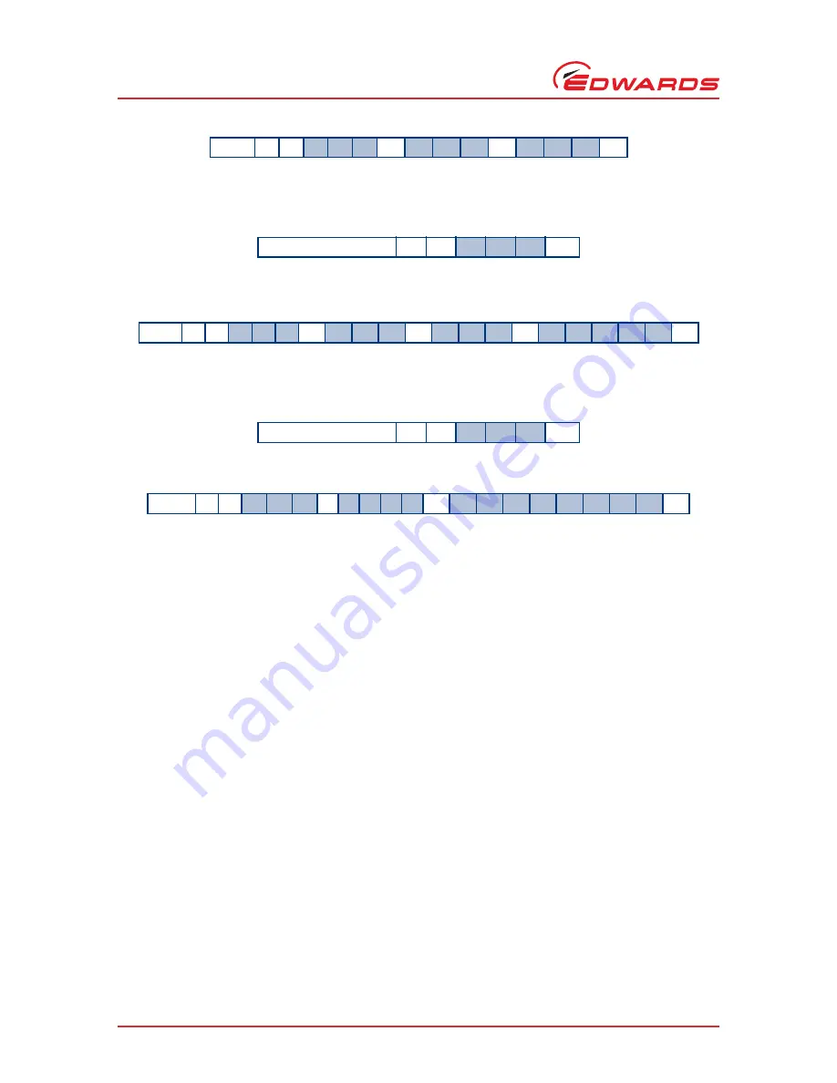
Link parameter readings
The internal voltage, current and motor power of the nEXT pump can be monitored by sending the following query:
The reply will be as follows (where the first number refers to voltage (measured in 0.1 Volts – i.e. divide the number
by 10 to get an answer in Volts), the second number refers to current (measured in 0.1 Amps) and the third number
refers to motor power (measured in 0.1 Watts)):
4.5.7
Measured motor speed
The measured rotational speed of the motor inside the nEXT pump can be monitored by sending the following query:
The reply will be as follows, where the first returned number refers to motor rotational speed in revolutions per
second (Hz):
Note:
The second return number is a 32-bit system status word (set of 8 hexadecimal characters) which is useful
for fault finding. Refer to
Section 5.5.9
for advice on decoding the system status word.
4.6
Mixed parallel and serial operation
In mixed parallel and serial operation the pump may receive commands from both serial and parallel interfaces. To
understand how these commands control the pump, refer to
Figure 19
. The pump will power up with ‘None in
Control’. From this state a parallel start signal or a serial start command may be received, resulting in the pump
moving to parallel control mode or serial control mode respectively. Serial start commands will only be received if
the serial enable line is active.
The state of the serial enable line may be switched between active and inactive whilst in mixed parallel and serial
operation. The primary function of the serial enable line is to enable the serial link. It has no direct effect on the
control mode. The pump will receive and respond to serial commands whenever the serial enable line is active, and
conversely will not receive or respond to serial commands when the serial enable line is inactive.
Availability of the parallel standby and fail signals depends on the state of the serial enable line and the position of
the RS485/RS232 switch as described in
Table 23
.
Reply
=
V
8
5
9
sp
d
d
d
;
d
d
d
cr
Command
?
V
8
6
0
cr
Reply
=
V
8
6
0
sp
d
d
d
;
d
d
d
;
d
d
d
d
d
cr
Command
?
V
8
5
2
cr
Reply
=
V
8
5
2
sp d
d
d
d
;
h
h
h
h
h
h
h
h
cr


