xvi
2000-DSS COMBINED SONAR
0009335_REV_D
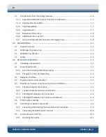
LIST OF FIGURES
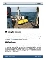
Figure 1-1: 2000-DSS Tow Vehicle being Prepared for Deployment ......................................................... 1-2
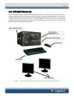
Figure 1-2: 2000 Topside Processor with Keyboard, Trackball, and two LCD Monitors ............................ 1-3
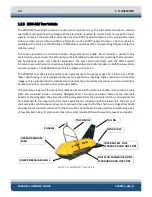
Figure 1-3: 2000-DSS Tow Vehicle ............................................................................................................. 1-4
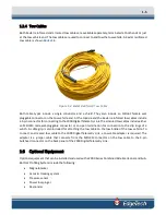
Figure 1-4: Kevlar Reinforced Tow Cable ................................................................................................... 1-5
Figure 3-1: Rack Mount Topside Front Panel ............................................................................................. 3-4
Figure 3-2: Rack Mount Topside Back Panel .............................................................................................. 3-5
Figure 3-3: System Cables .......................................................................................................................... 3-8
Figure 3-4: Tow Vehicle with Tow Cable Connected and Attached ........................................................... 3-9
Figure 3-5: DISCOVER 2000-C Dual Frequency Side Scan & DISCOVER Sub-Bottom Windows ............... 3-12
Figure 3-6: Lower Control Panel, Transmit Tab—DISCOVER Side Scan ................................................... 3-13
Figure 3-7: Options Dialog Box, Sonar Control Tab—DISCOVER Sub Bottom ......................................... 3-14
Figure 3-8: Options Dialog Box, Display Tab—DISCOVER Sub-Bottom .................................................... 3-14
Figure 3-9: 2000-DSS Tow Vehicle being Deployed ................................................................................. 3-17
Figure 3-10: Lower Control Panel, Bottom Track Tab—DISCOVER 200-C Dual Frequency Side Scan ..... 3-17
Figure 4-2: Location of Jumper JP6 on the Power Board of the FSIU ...................................................... 4-21
Figure 4-4: 2000 Digital Telemetry Link Electronics Block Diagram ........................................................ 4-22
Figure 4-5: 2000 Digital Telemetry Link Wiring Diagram ......................................................................... 4-23
Figure 4-7: Tow Vehicle Electronic Block Diagram................................................................................... 4-25
Figure 4-8: Tow Vehicle Interconnect Drawing........................................................................................ 4-26
Figure 4-9: Armored Cable, PMI Grip, Unterminated Topside ................................................................ 4-29
Figure 4-10: Test Cable ............................................................................................................................ 4-30
Содержание 2000-DSS
Страница 20: ......
Страница 56: ...Figure 4 2 2000 Digital Telemetry Link Electronics Block Diagram...
Страница 57: ...Figure 4 3 2000 Digital Telemetry Link Wiring Diagram...
Страница 59: ...Figure 4 4 Tow Vehicle Electronic Block Diagram...
Страница 60: ...Figure 4 5 Tow Vehicle Interconnect Drawing...
Страница 63: ...Figure 4 6 Armored Cable PMI Grip Unterminated Topside...
Страница 64: ...Figure 4 7 Test Cable...
Страница 77: ...5 13 Figure 5 16 Magnetic Declination Estimated Value Screen...
Страница 79: ...5 15 getDeclination CR Figure 5 18...
Страница 80: ......
Страница 94: ......
Страница 96: ......
Страница 98: ......


