4-19
4.0
TECHNICAL DESCRIPTION
This section provides an overall general description of the hardware elements comprising the 2000
Topside Processor and the 2000-DSS Tow Vehicle of the 2000 Series Combined Side Scan Sonar and Sub-
Bottom Profiling System. This information, which includes block diagrams, board descriptions, chassis
photos, component callouts, and wiring diagrams, can be useful for troubleshooting purposes and
installing optional equipment.
4.1
2000 Topside Processor
The 2000 Topside Processor is composed of the Topside Processor and the 2000 Digital Telemetry Link
installed in a 19-inch rack enclosure along with a keyboard, a trackball and two LCD monitors.
4.1.1
Topside Processor
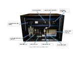
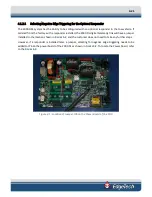
The Topside Processor electronics chassis is shown in
F
IGURE
4-1
. The main hardware elements in the
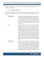
Topside Processor include the following components and circuit boards:
COMPUTER POWER SUPPLY
Provides DC power for the CPU Board and the hard drives.
CPU
The CPU board runs the Microsoft Windows XP operating system
and the DISCOVER software on an Intel Pentium 4, 2.4 GHz
processor and includes 512 MB of RAM. The CPU board outputs
downlink commands to the tow vehicle over the Ethernet
connection to the 2000 Digital Telemetry Link while it inputs the
uplink sonar data from the tow vehicle over the same
connection. A 500-GB hard drive contains the operating
software, and a 1-TB hard drive is used for data storage. Both
hard drives interface with the CPU board as do the LCD monitor,
the keyboard and the trackball. Power for the CPU board is
provided by the Computer Power Supply.
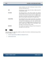
4-PORT RS-232 SERIAL BOARD
The 4-Port RS-232 Serial board plugs directly into the CPU and
provides four RS-232 serial ports on RJ45 connectors. A cable
connects from each connector to one of four DB-9 connectors,
COM5–COM8, on the back panel.
HARD DRIVES
A 160-GB hard drive (C:\ drive) stores the Windows XP operating
system and the application software. A 1 TB hard drive (D:\ drive)
is used for data storage.
Содержание 2000-DSS
Страница 20: ......
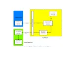
Страница 56: ...Figure 4 2 2000 Digital Telemetry Link Electronics Block Diagram...
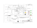
Страница 57: ...Figure 4 3 2000 Digital Telemetry Link Wiring Diagram...
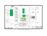
Страница 59: ...Figure 4 4 Tow Vehicle Electronic Block Diagram...
Страница 60: ...Figure 4 5 Tow Vehicle Interconnect Drawing...
Страница 63: ...Figure 4 6 Armored Cable PMI Grip Unterminated Topside...
Страница 64: ...Figure 4 7 Test Cable...
Страница 77: ...5 13 Figure 5 16 Magnetic Declination Estimated Value Screen...
Страница 79: ...5 15 getDeclination CR Figure 5 18...
Страница 80: ......
Страница 94: ......
Страница 96: ......
Страница 98: ......

