background image

C3A, C6A, C6A HDVideoColposcope User ManualApplication of the Video Colposcope Software 

- 47 - 


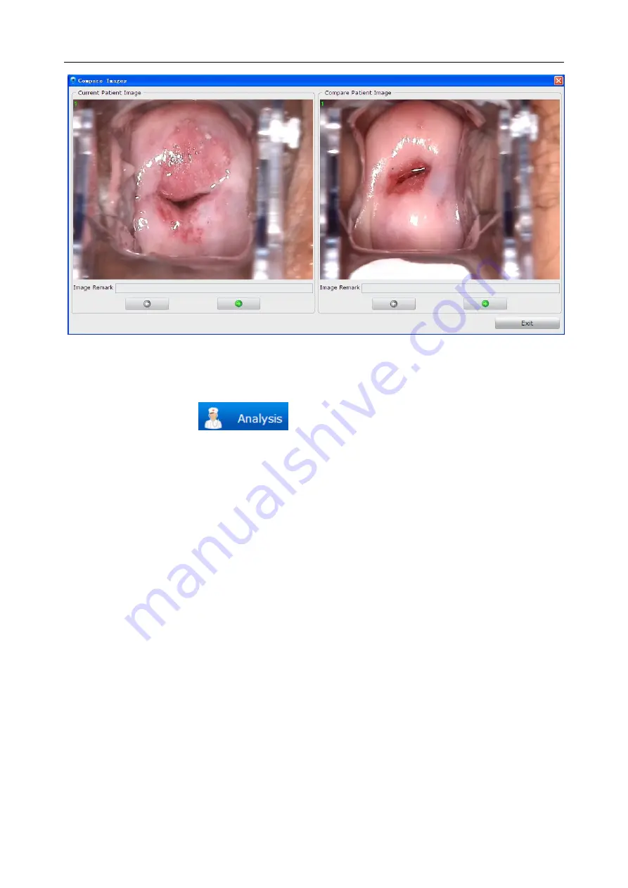
Figure 5-19 

5.4.6 Analyzing 

Click  the 

Analysis

  tag 

  to  switch  to  the 

Analysis

  interface.  For  specific 

operations on the 

Analysis

 interface, see section

5.5Analyzing

. 

5.4.7 Comparing Images 

Click the 

Compare

 button under the 

Current Patient Image

 area, the 

Current Patient Image 

Comparison

  page is  displayed. The system  compares  all images  of the current  patient.  If there 

are more than 6 images, the first 6 images are compared. For operations on this page, see section 

5.5.1Comparing Images of the Current Patient

. 

5.4.8 Editing an Image 

Right-click an image in the 

Current Patient Image

areaandchoose

Image Processing

.The

Image 

Processing

 page is displayed. You can edit the image on the 

Image Editing

 tab. 

1) Adding Image Remark 

In  the 

Image  Remark

  area,  input  remark  for  the  image,  then  click 

Save

  to  save  the  remark.  A 

maximum of 50 characters (excluding "&") can be inputted. This remark will be shown together 
with the image. 

2) Adding Image Notes 

You can add notes on the image as follows: In the 

Image Note

 area, click 

Note

. Then move the 

cursor to the image area and click on it. A broken line frame is shown, and you can type note in it. 
You  can  move  the  cursor  to  other  positions  to  add  more  notes.  After  all  notes  are  added,  click 

Содержание C3A

Страница 1: ...三 ...

Страница 2: ...formation and patent information are contained in this manual the user shall not disclose such information to any irrelevant third party The user shall understand that nothing in this manual grants him expressly or implicitly any right or license to use any of the intellectual properties of EDAN EDAN holds the rights to modify update and ultimately explain this manual Responsibility of the Manufac...

Страница 3: ...A CAUTIONlabel advises against actions or situations that could damage equipment produce inaccurate data or invalidate a procedure NOTE A NOTE provides useful information regarding a function or a procedure ...

Страница 4: ... 1 Placing Moving the Stand 21 3 3 2 Adjusting the Camera Stand Height 22 3 3 3 Adjusting the Camera Angle 23 3 3 4 Adjusting the Position of Keyboard Tray or Laptop Tray 24 3 3 5 Adjusting the Monitor Angle 24 3 4 Adjusting the MT 806 Trolley 24 3 4 1 Placing MovingtheTrolley 24 3 4 2 Adjusting the Monitor Angle 24 3 5 Connecting the Power Adapter 25 3 6 Switching on the System 25 3 7 Switching o...

Страница 5: ...ation Report 63 5 6 2 Changing Print Settings 64 5 6 3 Selecting a Print Template 65 5 6 4 Exporting the Report 65 5 6 5 Sending the Report to PACS 66 5 6 6 Emailing the Report 66 5 7 Report 66 5 8 Operation Record 67 5 8 1 Printing the Operation Report 68 5 8 2 Specifying the Record 68 5 8 3 Changing Print Settings 69 5 8 4 Selecting a Print Template 69 5 8 5 Emailing the Report 69 5 9 History Ca...

Страница 6: ...ing Auto Capture 84 5 12 2 17 Setting Capture Mode 84 5 12 2 18 Restoring to Factory Configuration 84 5 12 2 19 Setting Bar Code Scanner 84 5 12 2 20 Module Customization 85 5 12 3 Database Management 85 5 12 3 1 Backing up Database 85 5 12 3 2 Restoring Database 86 5 12 3 3 Exporting Terms 86 5 12 3 4 Importing Terms 86 5 12 4 Network Setup 87 5 12 4 1 Enabling DICOM 87 5 12 4 2 Enabling the Emai...

Страница 7: ... Appendix 4 EMC Information 101 A4 1 Electromagnetic Emissions 101 A4 2 Electromagnetic Immunity 102 A4 3 Electromagnetic Immunity 104 A4 4 Recommended Separation Distances 107 Appendix 5 Abbreviation 109 ...

Страница 8: ... home use or to touch the patient 1 2 Safety Precautions WARNING and CAUTION messages must be observed To avoid the possibility of injury observe the following precautions during the operation of the device WARNING 1 This device is provided for the use of professionally trainedandqualified physicians or under guidanceof these personnel Familiarize yourself with the contents of this user manual bef...

Страница 9: ...st be used outside the patient environment and the system should be tested according to the requirements of IEC EN 60601 1 10 Do not exceed the maximum permitted load when using multiple portable socket outlets to supply the system You can refer to the label or silk screen for the maximum permitted load 11 SHOCK HAZARD Do not connect non medical electrical equipment which has been supplied as a pa...

Страница 10: ... service or maintain the device or any accessory which is in use with a patient 26 Assembly of the device and modifications during actual service life shall be evaluated based on the requirements of IEC60601 1 CAUTION 1 The device is designed for continuous operation Do not water the device 2 Keep the environment clean Makethe device far from corrosive medicine dust area high temperature and humid...

Страница 11: ...nd other persons touching parts of the system reference IEC 60601 1 It is difficult to apply unique dimensions to the volume and the dimensions given in the figure below have been justified Examination table 1 5 m Overhead view Floor 1 5 m 1 5 m 2 5 m Examination table Side view Figure 1 1Patient environment 1 3 Definitions and Symbols No Symbol Description 1 Stand by 2 Caution 3 USB connection 4 ...

Страница 12: ...t output 8 CLASS II equipment 9 Consulting instructions 10 Consult instruction for use on this website 11 Foot switch 12 Part Number 13 SERIAL NUMBER 14 General symbol for recovery recyclable 15 Date of manufacture 16 AUTHORISED REPRESENTATIVE IN THE EUROPEAN COMMUNITY 17 MANUFACTURER 18 CE marking ...

Страница 13: ...on in water 22 Refer to instruction manual booklet Background Blue Symbol White 23 General warning sign Background Yellow Symbol Outline Black 24 No sitting Background White Symbol Black Outline Red 25 No stepping on surface Background White Symbol Black Outline Red 26 No Pushing Background White Symbol Black Outline Red 27 Mind your fingers Background Yellow Symbol White and black Outline Black 2...

Страница 14: ...off NOTE 1 The user manual is printed in black and white 2 The symbol marked with an asterisk is only applicable to C3A and C6A 3 The 9th symbol applies to paper user manual 4 The 10th symbol applies to electronic user manual 5 If both paper user manual and electronic user manual are configured the paper user manual shall prevail ...

Страница 15: ...version of the system standard IEC EN 60601 1 If any question consult our technical service department or your local distributor 2 For any non medical electrical equipment forming part of the system to be used within the patient environment additional protective earthing should be applied or the non medical electrical equipment should be supplied via a separating transformer that complies with IEC...

Страница 16: ...r 1920 1080 2 1 2 Monitor Requirements C3A C6A Interface S video Resolution 1024 768 C6A HD Interface HDMI DVI Resolution 1920 1080 WARNING 1 The computer or monitor shall comply with the requirements of the valid version of IEC EN 60950 and have relevant certification such as the CE certification 2 When connecting the computer or monitorto the device ensure that the formed system meets the requir...

Страница 17: ...fication of C6 is 1 36X and can be set to 1 50X the magnification of C6 HD is 1 50X and can be set to 1 60X 2 2 1 Appearance Figure 2 2 C3A C6A C6A HD Camera 1 Key panel 2 Camera handle trigger 3 Camera handle 4 Camera lens 5 LED lamps 6 Lens cap 2 2 2 Keys Figure 2 3 Camera panel keys 1 Stand by switch Function Switch on or off the camera 1 2 3 4 5 6 ...

Страница 18: ...this key to pull close the focus 5 FREEZE key Function Freeze or unfreeze the current image Operation Press this key to freeze the current image and is shown on the screen Press it again to unfreeze the image 6 TIME key Function Activate or deactivate timer Operation Press this key to activate timer The screen shows a time mark as T0 00 which will automatically disappear after it counts to T2 59 B...

Страница 19: ...agnification is shown on the screen after you press this key and will disappear 3 seconds later If display of magnification information is enabled the magnification is always shown on the screen 11 Camera handle trigger Function Control coordinate display capture images or display six images Operation If this trigger is set to control coordinate display pull this trigger the screen displays a coor...

Страница 20: ...nt knob 2 Horizontal angle adjustment knob 3 Stand post 4 Camera holder 5 Lifting post 6 Height adjustment knob 7 Chassis 8 Casters 2 4 Swing Arm Stand By default the swing arm stand includes the camera stand part The monitor supporter part keyboard tray part and laptop tray part are optional The swing arm stand in maximum configuration is as follows 1 2 3 7 8 4 5 6 1 2 3 7 8 4 5 6 ...

Страница 21: ...C3A C6A C6A HDVideoColposcope User Manual Introduction 14 Figure 2 6 Swing arm stand with the monitor supporter part and keyboard tray part 1 2 3 4 10 12 14 5 7 8 13 6 9 11 ...

Страница 22: ...ost 10 Keyboard tray 11 Tray arm 12 Stand post 13 Chassis 14 Casters 15 Mouse tray 16 Laptop tray The monitor or all in one PC can be installed on the monitor supporter The keyboard can be placed on the keyboard tray The laptop can be placed on the laptop tray The mouse can be placed on the mouse tray which can be pushed inward when not needed CAUTION The maximum load of the monitor supporter is 7...

Страница 23: ... keyboard can be placed on the upper tray The mouse can be placed on the mouse tray which can be pushed inward when not needed The printer can be placed on the lower tray You can put small miscellaneousobjects in the upper drawer and printing paper in the lower drawer CAUTION The maximum load of the monitor supporter is 7 5 kg that of the upper tray is 10 kg that of the mouse tray is 0 5 kg that o...

Страница 24: ...ure box 1 DC port used for connection with the power adapter 2 USB B interface used for connection with the computer 3 3 pin aviation interface used for connectionwiththefoot switch 4 4 pinaviation interface used for connection with the monitor 2 7 Movable Video Capture Box The movable video capture box applies to both the vertical stand and swing arm stand It can be installed on horizontal arm 2 ...

Страница 25: ... aviation interface used for connection with the foot switch 2 USB B interface used for connection with the computer 3 DC port used for connection with the power adapter 4 Power switch 5 HD signal output interface used for connection with the monitor 6 HD signal input interface used for connection with the camera 2 8 Foot Switch A foot switch is provided You can capture images by simply stepping o...

Страница 26: ... package for possible future transportation or storage 3 2 Adjusting the Vertical Stand 3 2 1 Placing Moving the Stand Each stand caster has a pedal Step down the pedal can lock the caster When the stand is placed somewhere step down the pedals to lock the casters and stop the stand from moving around When you need to move the stand hold the lifting post with your hand and then push up the pedalst...

Страница 27: ...ost with one hand to avoid sudden fall of the camera 3 2 3 Adjusting the Camera Angle To get a clear image you may need to adjust the camera angle Follow the instructions To adjust horizontal angle Hold the camera handle with your left hand and rotate the horizontal angle adjustment knob anticlockwise with the other hand Now you can tilt the camera left or right to the proper angle Rotate the adju...

Страница 28: ...nd then push up the pedalsto release the casters After you move the stand to the destination step down the pedals again CAUTION 1 Do not move the stand by holding the camera handle otherwise the camera may be damaged 2 When moving the stand avoid the camera from hitting the door frame or other objects 3 If the laptop tray or keyboard tray is configured remove the laptop or keyboard placed on the t...

Страница 29: ...ight then release your hand To increase the height Hold the swing arm with your hand and lift it up to the desired height then release your hand Figure 3 4 Due to the locking force of the gas spring inside the swing arm the swing arm can fix at the position after you release your hand The adjustment hole of the gas spring is in the swing arm axle connecting horizontal arm 2 as shown in the followi...

Страница 30: ... at points A B and C Follow the instructions Point A Hold horizontal arm 2 with one hand and rotate the swing arm to the desired position on the horizontal direction with the other hand Point B Hold the swing arm with one hand and rotate horizontal arm 1 to the desired position with the other hand Point C Hold horizontal arm 1 with one hand and rotate the holder post to the desired position by rot...

Страница 31: ... of the monitor with both hands then tilt it left or right to the desired angle To adjust vertical angle Hold the top and bottom sides of the monitor with both hands then tilt it up or down to the desired angle CAUTION When tilting the monitor be careful not to jam your hands between the monitor supporter and the monitor 3 4 Adjusting the MT 806 Trolley 3 4 1 Placing MovingtheTrolley Each trolley ...

Страница 32: ...60Hz 3 6 Switching on the System Prior to switching on the system check if all the components are correctly connected and if all the cables are in good condition Then turn on the camera If the movable video capture box is used first turn on its power switch then the camera 3 7 Switching off the System When the examination is completed exit the video colposcope software Turn off the camera and cove...

Страница 33: ...that all the equipment forming the system has been connected and the camera has been switched on Before software installation close any antivirus software Replace or update of the software must be performed by professional personnel of EDAN or under their guidance 1 Open the CD The available directories files and programs are as follows Figure 4 1 2 Double click The following interface is displaye...

Страница 34: ...oColposcope User ManualSoftware Installation 27 Figure 4 3 It takes some time for the software installation preparation Please wait When the installation is ready the following interface is displayed ClickNext Figure 4 4 ...

Страница 35: ...pt is displayed Click Next after you check the items Figure 4 5 5 Click Browse to select the installation path The default path D Cx Cx_Workstation is recommended Then click Next Figure 4 6 NOTE If disk D does not exist in the system the default path is invalid Please select another path ...

Страница 36: ...ion 29 6 ClickBrowse to select the database installation path Do not select C Program Files The default path D Cx Cx_Database is recommended Then click Next Figure 4 7 7 ClickNext to continue installation Do not close the black command prompt windows Figure 4 8 ...

Страница 37: ... 30 Figure 4 9 Figure 4 10 For operating system Windows 7 Windows 8 Windows 8 1 or Windows 10 a prompt will be displayed asking you whether to install the software driver Choose to install the driver as shown in the following figure Windows 8 is used as an example ...

Страница 38: ...e capture card on the Setup interface a system prompt will be displayed indicating that initializing video module failed For details about the troubleshooting see relevant descriptions in A2 2 Access to Video Colposcope Software with Error Reporting 8 ClickFinish to complete the installation Figure 4 12 After installation the software icon is available on the PC desktop ...

Страница 39: ...on the desktop The system login interface is displayed Figure 5 1 The drop down menu of Name lists all existingusernames Select your username input the correct password and then click Login Your username is shown on the top of the displayed main interface for example For the first login use the name sys and the default password is sys After you log in to the system you can add more users by using ...

Страница 40: ... 3 Operation interface It corresponds with the buttons in the tool bar 4 Status bar It calculates the number of patients examined and to be examined 5 3 Patient Information The system displays the Patient Info operation interface after login On another interface you can click the Patient Info button in the tool bar to switch to this interface On this interface you can input patient information vie...

Страница 41: ...k to hide the patient information again Figure 5 4 On the Indications for Colposcopy tab select the clinical indication and input information about TCT HPV or histopathology based on the patient s actual conditions Figure 5 5 NOTE Examining Time can only be the current day or an earlier day For Reason TCT HPV and Histopathology you can manually input the information or click to open the Select Ter...

Страница 42: ...C3A C6A C6A HDVideoColposcope User ManualApplication of the Video Colposcope Software 35 down a term Figure 5 6 ...

Страница 43: ...tart this patient is added and the system enters theExamine interface automatically You can clickClear to delete all the inputted information 5 3 2 Viewing Today s Exam Schedule Today s exam schedulelistsallpatients of the current day who have been examined orareto be examined By default the list is sorted based on Item and Status as follows Unexamined patients are listed preceding examined patien...

Страница 44: ...tion Record This patient s examination record is displayed You can only view the examination recordbut cannot edit it 5 3 4 Modifying Patient Information Select a patient in the list right click it and choose Modify Patient Information On the displayed page you can modify the patient information Then click OK to confirm the modification or click Exit to cancel it Figure 5 9 NOTE 1 If a patient in ...

Страница 45: ...ase is deleted as well 5 3 6 Searching for a Re examined Patient To quickly search for an examined patient perform the following procedures In the Re examination Search area select a condition then input the keyword If the condition is Name Patient No orDOB the system supports fuzzy search and you can search by inputting only part of the keyword The more information you input the more accurate res...

Страница 46: ...he Appointment interface Input information such as patient name age and appointment time on the Patient Info tab and indications on the Indications for Colposcopy tab then click Save The appointment is made and the patient s information is shown in the appointment list below The appointment time can be the current day or a future day If the user type of the doctor login is nurse the system will mo...

Страница 47: ...s after it Click Search all the patients that meet the conditionwill be listed Click Refresh the original appointment list is shown again 5 3 9 Modifying an Appointment Select a patient in the appointment list her appointment information is shown above You can edit the information and then click Modify A prompt is issued Click OK to confirm the modification or click Cancel to cancel it 5 3 10 Dele...

Страница 48: ...he patient if changed toTo Appointment the system will make the appointment for the patient and the Appointment interface shows this appointment record in which the appointment time is the follow up date Input search conditions in the Search area and click Search all the patients that meet the conditions will be displayed in the follow up list Click Refresh the original follow up list is shown aga...

Страница 49: ...u want to input Among the items Patient No NameandAge are selected by default and can t be modified The rest items are selected by default and can be modified After the modification click Save and Modification succeeded will be displayed 5 3 14 Worklist Users can search records and download them to local file on PACS server through this function Enable DICOM function for details please refer to Se...

Страница 50: ...es NOTE 1 You can open the Examine interface only after the camera is connected to the computer and switched on 2 If no image is displayed check whether the USB connection between the computer and the video capture box is normal 5 4 1 Examination Prompts If the function of providing examination prompts is enabled see section 5 12 2 15Enabling Examination Prompts prompts are available when you open...

Страница 51: ...ccording to the prompts Figure 5 16 NOTE After you press the TIME key the Auto CaptureandHelptags become unavailable They are available again after you press the TIME keyagain or the current timer ends Click the Capturetag the system captures the current image The captured image is shown on the right of the screen A maximum of 50 images can be captured for a patient You can double click an image t...

Страница 52: ...he Videotag the system starts taking video Click the Stoptag to stop taking video The video taking can last for at most one hour Once one hour is reached the system automatically stops taking video The video is saved as an avi file and the file is shown with a video symbol on the right of the screen You can double click to playthe video and capture images during video playing 5 4 4 Viewing in Full...

Страница 53: ...nt information and image of the first case in the list You can click a desired case in the Case List so that its patient information and image are displayed in the Compare Patient Information area Figure 5 18 NOTE For a re examined patient the Compare Patient Information area displays her last examination record and the Case List shows all of her examination records with the latest examination rec...

Страница 54: ...n 5 5 1Comparing Images of the Current Patient 5 4 8 Editing an Image Right click an image in the Current Patient ImageareaandchooseImage Processing TheImage Processing page is displayed You can edit the image on the Image Editing tab 1 Adding Image Remark In the Image Remark area input remark for the image then click Save to save the remark A maximum of 50 characters excluding can be inputted Thi...

Страница 55: ...L Once a font is selected it applies to all notes To modify note content click the note the cursor flashes and the note becomes editable Modify the content and then click Save in the Image Note area To move a note click and drag the note to the target position Then clickSave in the Image Note area To delete a note right click the note and choose Delete The note is deleted Then clickSave in the Ima...

Страница 56: ...ed You can measure the image on the Image Measuring tab Perform calibration before measuring the image You can choose manual calibration or default calibration NOTE 1 If you choose default calibration keep the camera at a distance of 25cm from the target in vertical direction while capturing images and make the calibration magnification consistent with the actual magnification 2 In default calibra...

Страница 57: ...nt data right click it and choose Delete You can click Clear Data to clear all the measurement data on the image Clear Save the current image with all the measurement data on it will be saved as a new image and displayed in the patient image list If you switch to the Image Editing tab the measurement data will be cleared 3 Compute Lesion Percentage a Select lesion compute function b Select the les...

Страница 58: ...e Analysis interface or you can click the Analysis tag on the Examine interface to switch to the Analysis interface On this interface you can perform R way evaluation RCI evaluation and Swede evaluation and input examination result and biopsy result Figure 5 23 5 5 1 Comparing Images of the Current Patient In the Current Patient Image area select two or more images right click and choose Compare o...

Страница 59: ...C3A C6A C6A HDVideoColposcope User ManualApplication of the Video Colposcope Software 52 Figure 5 24 Figure 5 25 ...

Страница 60: ... it Click Combine images on the comparison page are combined into one image which is also displayed in the Current Patient Image area In the Current Patient Image area select an image right click it and choose Delete the image will be deleted You can select multiple images and delete them at the same time Figure 5 26 Click Select All all the images will be selected Click Select None all the images...

Страница 61: ... test images acetic acid solution test images and Lugol s iodine test images observe whether there are continuous hemorrhagic spots and make labels as required The system will offer colposcopic preliminary diagnose and treatment suggestion based on your observation and labels Figure 5 27 1 Labeling area 2 Image preview area 3 Evaluation step area When the cursor is placed on an image in the Curren...

Страница 62: ...p again If endocervical curettage ECC or diagnostic conizationis recommended select ECC or Diagnostic Conization Click Accept the system switches to the Examination Record tab and the preliminary diagnosis and treatment suggestion are loaded to the Examination Record tab and information about the recommended biopsy regions is loaded to the Biopsy Record tab If there is any immediate biopsy region ...

Страница 63: ... HDVideoColposcope User ManualApplication of the Video Colposcope Software 56 Figure 5 29 Colposcopy examination Click the Select Term page is displayed Figure 5 30 Selection of termsforcolposcopic findings cervix ...

Страница 64: ...vagina Figure 5 32 Selection of terms for colposcopic findings vulvar Terms of colposcopic findings are listed on the left and classified into four categories Normal Abnormal Suspicious For Invasion and Miscellaneous Finding Double click a term this term is added to the Selected Term area You can select multiple terms and edit them Click OK the ...

Страница 65: ... you want to delete the current reference image click Del Ref Image A prompt is issued asking you to confirm the deletion Click OK the current reference image is deleted You can also click Term Maintenance and maintain terms on the displayed Term Maintenance page Under Colposcopic Primary Diag you can manually input preliminary diagnose and treatment or select relevant terms by using the button ne...

Страница 66: ...ge L Once a font is selected it applies to all notes After you add an immediate biopsy region thePost examination Noticefield will automatically add the first term in the remark term list and when all immediate biopsy regionsare deleted the content in thePost examination Notice field will be cleared Figure 5 34 If you want to delete a note select this note in the list and click Del Selected Note I...

Страница 67: ...available in the United States On the RCI Evaluationtab you can perform RCI Reid Colposcopic Index evaluation Figure 5 35 RCI evaluation is performed based on four aspects colour margin vessel and Iodine staining Click the button the corresponding Select Term page is displayed In the term list each term has its score ...

Страница 68: ...he score of this aspect is the largest value among the scores of the selected terms The system will calculate the total score and provide the RCI evaluation result based on this score NOTE You can modify terms of RCI evaluation but you cannot modify term scores or add delete or move up or down any term When you first enter the Term Maintenance page the Add Save Delete Up and Down button are invali...

Страница 69: ...e Swede Evaluationtab you can perform Swede evaluation Figure 5 37 Swede evaluation is performed based on five aspects aceto uptake margin surface vessel lesion size and Iodine staining Operations on the Swede Evaluation tab are similar to those on the RCI Evaluation tab see section 5 5 6Performing RCI Evaluation for reference 5 5 8 Saving Analysis Result After inputting all the analysis result cl...

Страница 70: ...e captured images are shown on the right If six images of the patient have been combined into one image using the combination function see section5 5 1Comparing Images of the Current Patient the examination report will show these images by default according to the following principle Print Template Images Shown on the Report 1 image 5th image 2 images 5th and 6th images 3 images 1st 5th and 6th im...

Страница 71: ...ePrinttag on the left of the interface to start printing the report To obtain an optimal report you are advised to set the print items first NOTE 1 You can double click an image in the Current Patient Image list to magnify it and double click the magnified image or click on it to exit magnification 2 If multiple images are available click on the left or right of the magnified image to view the pre...

Страница 72: ... and report title applies to all print templates 5 6 3 Selecting a Print Template Five standard print templates are available 1 image template 2 image template 3 image template 4 image template and 6 image template These five templates contain the same print items except for the number of images You can select a print template on the Setup page or you can quickly select the print template by click...

Страница 73: ...result doctor and hospital information etc to the server 4 During the sending process if the system is disconnected from the server the system will stay in the sending state You can restart the software and click To PACS again 5 6 6 Emailing the Report On the Report interface click theEmailtag on the left to send the report to the specified email address NOTE The Email tag is shown on the Report i...

Страница 74: ...igure 5 40 NOTE The Report Module needs to be set in Setup for details please refer to 5 12 2 20Module Customization 5 8 Operation Record You can record the operation process and print the operation report Click the Operation button in the tool bar to open the Operation interface Figure 5 41 ...

Страница 75: ...nt Patient Image list to the Image area of the report Click thePrinttag on the left of the interface to start printing the report 5 8 2 Specifying the Record On the Operation interface click the Record tag on the left to open the Recordpage On this page you can specify operation related information The specified items will be shown on the operation report Figure 5 42 For the follow up date you can...

Страница 76: ...late Five standard print templates are available 1 image template 2 image template 3 image template 4 image template and 6 image template These five templates contain the same print items such as patient information content page header and footer except for the number of images You can select a print template on the Setup page or you can quickly select the print template by clicking the or tag on ...

Страница 77: ...page turning buttons are provided If there are multiple pages you can click to switch to the first page click to switch to the previous page click to switch to the next page or click to switch to the last page Alternatively you can input the page number in the blank and click NOTE 1 You can double click an image to magnify it and double click the magnified image or click on it to exit magnificatio...

Страница 78: ...re 5 44 Figure 5 44 Choose Clear Attention or click the cell again the attention label will be cleared Choose Setup the following page is displayed Figure 5 45 There are five attention labels in total You can customize the name or color for each label or change the default label then click Save ...

Страница 79: ...dit it 5 9 4 Browsing Patient Report Select a case in the list right click it and choose Browse Patient Report The patient report is displayed You can only view it but cannot edit it 5 9 5 Modifying Patient Information Select a case in the list right click it and choose Modify Patient Information or click the Modify Patient Information button at the bottom of the interface On the displayed Modify ...

Страница 80: ...tients examined by other physicians while other types of users having this permission can only modify the operation records of patients examined by themselves 5 9 8 Modifying Patient Report Double click a case in the list The system switches to the Report interface and you can modify the patient report for example you can modify print setup change print template or replace the images shown on the ...

Страница 81: ...elect a case in the list right click it and choose Export Data On the displayed dialog box select a directory and click OK The patient data is exported to the target directory You can select multiple cases and export them at the same time 5 9 12 Importing Patient Data Select a case in the list right click it and choose Import Data On the displayed dialog box select a directory and click OK The pat...

Страница 82: ...the right including Name Description Patient List It lists all the cases that meet the condition Data Comparison It shows the quantity and proportion of each item that meet the condition Chart It shows data comparison by chart and three formats are provided Linear Graph Histogram and Pie Chart Click a chart format the chart is then shown in the corresponding format Linear Graph Figure 5 47 ...

Страница 83: ...d into an Excel file After performing statistics click theExportRecord button Select a directory input the file name and then click Save TheExcel file is saved in the target directory NOTE 1 The operation of exporting patient list or chart can be performed only by users having the permission of exporting record chart otherwise the system will issue a prompt indicating that you are unauthorized ...

Страница 84: ...l file is saved in the target directory 5 11 Switching User You can switch user without exiting the system Click the Switch Userbutton in the tool bar to open the Switch User interface Figure 5 50 Select a username and input the correct password Click Login the user is switched Or click Exit the previous user remains 5 12 System Setup NOTE Only users having the permission of system setup can open ...

Страница 85: ... be the same as Password in the UserInfo area Click the buttonnext to Signatureto import an imageof the user s signature and select the authority 3 Click Add This user is added to the User List on the right 4 Click OK 5 Exit the system and restart the software immediately NOTE 1 The user s signature image should be in jpg format and cannot exceed 512KB For clear display on the report it is recomme...

Страница 86: ...eneral Setup 5 12 2 1 Changing Date Format 1 Click the Setupbutton to open the Setupinterface 2 On the General Setuptab choose a date format from the Date Format drop down menu 3 Click OK 4 Exit the system and restart the software immediately NOTE The date is shown in the same format as that of the operating system by default unless the date format is changed 5 12 2 2 Setting Follow up Period 1 Cl...

Страница 87: ...isplay and display6 image 1 Click the Setupbutton to open the Setupinterface 2 On the General Setup tab selectCaptureImage or Display Coordinate in the Camera Handle Trigger Setup area 3 Click OK 4 Exit the system and restart the software immediately 5 12 2 5 Setting the Video Capture Card 1 Click the Setupbutton to open the Setupinterface 2 On the General Setup tab click the Capture Card Setup bu...

Страница 88: ...amining Time are mandatory and cannot be deselected 2 Attention is always shown in the first row and cannot be moved 5 12 2 7 Enabling the Report Export Function 1 Click the Setupbutton to open the Setupinterface 2 On the General Setuptab selectExportin the Printing area 3 Click OK 4 Exit the system and restart the software immediately NOTE The Export tag is shown on the Report interface only afte...

Страница 89: ...able UAC move the slidertoNever notify and clickOK If the system asks you to enter administrator password please input it and restart your computer 5 12 2 10 Enabling Patient Appointment 1 Click the Setupbutton to open the Setupinterface 2 On the General Setuptab selectReservations Appointmentsin the Others area 3 Click OK 4 Exit the system and restart the software immediately 5 12 2 11 Enabling R...

Страница 90: ... Click the Setupbutton to open the Setupinterface 2 On the General Setuptab selectRCI Evaluationin the Others area 3 Click OK 4 Exit the system and restart the software immediately NOTE 1 RCI Evaluation is selected by default You can deselect it to disable the function 2 The RCI evaluation is not available in the United States 5 12 2 14 Enabling Swede Evaluation 1 Click the Setupbutton to open the...

Страница 91: ...n the Examine interface to enable or disable auto capture 5 12 2 17 Setting Capture Mode Two modes are available screening the default mode and diagnose The system provides more image capture prompts if enabled and captures more images with the auto capture function if enabled in diagnose mode than in screening mode 1 Click the Setupbutton to open the Setupinterface 2 On the General Setuptab selec...

Страница 92: ...port Operation Database Statistics Switch User and Exit are selected by default and can be modified Report Edit Content Analysis and Report cannot be selected simultaneously 3 After the modification click Save and The setting change will take effect when running the software next time Please restart the software will be displayed Click OK and restart the software the modified setup will take effec...

Страница 93: ...he target directory 4 Click OKafter exporting is completed NOTE For terms with reference images their reference images will also be exported to the target directory 5 12 3 4 Importing Terms 1 Click the Setupbutton to open the Setupinterface 2 On the Database tab click in the Import Term area to select the directory in which terms to be imported are stored 3 Click Import Term The system asks you to...

Страница 94: ...me otherwise the images will be sent in single frame if you selectSend Report the report will be sent to the PACS server in picture form 4 Input DICOM WORKLIST Setup including the PACS IP Port Number Calling AE Title and Called AE Title according to your server configuration PACS IP PACS server IP address Port Number Port number of the PACS server Calling AE Title Input it according to the server ...

Страница 95: ...eded click Save If sending the test email failed change the email setting and test again 6 After successful setting click Exit NOTE You can input several email receiver addresses separating them with a semicolon 5 13 Exit Click the Exitbutton in the tool bar A prompt is issued Click Yes to exit the system or click No to keep the system ...

Страница 96: ...egulations and each time after service The equipment should undergo periodic safety testing to ensure proper patient isolation from leakage currents This should include leakage current measurement and insulation testing The recommended testing interval is once a year or as specified in the institution s test and inspection protocol WARNING Failure on the part of the responsible individual hospital...

Страница 97: ...ning cloth and wipe the lens gently 3 Clean the lens with a soft dry cloth CAUTION 1 The device components are not waterproof Do not immerse any components in water or allow liquids to enter the cases 2 In case of liquid splashing on the equipment wipe it with dry cloth immediately to stop the liquid from entering the interior Stop using the device and contact the service personnel if accidental w...

Страница 98: ...are Ethanol 75 Isopropanol 70 Clean the device prior to disinfection Disinfecting the device 1 Switch off the system and remove the power cord 2 Wipe the external surface of the device components camera and cables using a soft cloth dampened with the disinfectant 3 Wipe the surface dry with a soft dry cloth Make sure that no liquid enters the cases and the surface must be wiped clean in the end ...

Страница 99: ...N d damage caused by accidents e replacement or removal of serial number label and manufacture label If a product covered by this warranty is determined to be defective because of defective materials components or workmanship and the warranty claim is made within the warranty period EDAN will at its discretion repair or replace the defective part s free of charge EDAN will not provide a substitute...

Страница 100: ...ng arm stand 45kg Safe Load MT 806 trolley 30kg Power Supply Operating Voltage 100V 240V Input Current 400mA 200mA Power Adaptor FW7556M 12 Input Current 500mA 200mA Power Adaptor ME20A1202F01 Operating Frequency 50 Hz 60 Hz Standards Compliance IEC 60601 1 2005 A1 2012 EN 60601 1 2006 A1 2013 IEC 60601 1 2 2014 EN 60601 1 2 2015 Anti electric Shock Type Class II equipment Power Adaptor FW7556M 12...

Страница 101: ...Focus mode Manual Auto Output signal S Video Video mode PAL NTSC System resolution 500 TVL Space resolution 10 lp mm Image geometric distortion 3 Camera light source White loop group LED light White balance Auto Manual Imaging mode White light 3 levels Electronic green filter 3 levels SNR 50dB Depth of field 6X 120mm 18X 5mm C6A HD Essential Performance Magnification 1 60X Operation distance 200 m...

Страница 102: ...s 95 System resolution 900 TVL Space resolution 14lp mm Image geometric distortion 3 Camera light source White loop group LED light White balance Auto Manual Imaging mode White light 3 levels Electronic green filter 3 levels SNR 50dB Depth of field 6X 120mm 18X 5mm ...

Страница 103: ...el Administrative Tools Services and enable postgresql 8 3 A2 2 Access to Video Colposcope Software with Error Reporting Phenomenon Possible Cause Solution Video module initialization fails The video driver breaks down Restart the computer The video capture card is faulty Check the video capture card The USB DC cable or USB cable is loose Fasten the cable The driver of the video capture card has n...

Страница 104: ... the software installation package and find the usbdriver USBToCOMdirectory If the 32 bit operating system is used open the X32 folder right click installUSBtoCOM bat and choose Run as administrator If the 64 bit operating system is used open the X64 folder right click installUSBtoCOM bat and choose Run as administrator Unsuccessful connection to the printer Select the incorrect printer in the pri...

Страница 105: ...cable or USB cable is damaged Replace the cable The parameters of the video capture card are set to incorrect values Restore the parameters to default values The connecting cable in the camera is loose Remove the plastic cover to check it The board in the camera is damaged Replace the board The signal input cable in the video capture box is loose Open the video capture box to check it The shooting...

Страница 106: ...e drive circuit is faulty Replace the control board The connecting cable is damaged Replace the connecting cable The connecting cable is loose Fasten the connecting cable The keysare not sensitive or cannot control the camera The circuit is faulty Replace the control board and key board The connecting cable is damaged Replace the connecting cable The connecting cable is loose Fasten the connecting...

Страница 107: ...or ME20A1202F01 01 21 064361 Power Plug European Standard 01 12 032101 Power Plug American Japanese Standard 01 12 032102 Power Plug Australian Standard 01 12 032103 Power Plug Argentine Standard 01 12 032104 Power Plug Indian Standard 01 12 032105 Power Plug Brazilian Standard 01 12 032106 USB DC cable 01 13 036677 USB cable 01 13 036779 S Video cable for C3A C6A 01 13 036657 HDMI standard cable ...

Страница 108: ...liance Electromagnetic environment guidance RF emissions CISPR 11 Group 1 The Video Colposcope uses RF energy only for its internal function Therefore its RF emissions are very low and are not likely to cause any interference in nearby electronic equipment RF emission CISPR 11 Class A The Video Colposcopeis suitable for use in all establishments other than domestic and those directly connected to ...

Страница 109: ... wood concrete or ceramic tile If floor are covered with synthetic material the relative humidity should be at least 30 Electrical fast transient burst IEC 61000 4 4 2 kV for power supply lines 1 kV for input output lines 2kV for power supply lines Not Applicable Mains power quality should be that of a typical commercial or hospital environment Surge IEC 61000 4 5 1 kV line s to line s 2 kV line s...

Страница 110: ...225 270 and 315 0 UT 1 cycle and 70 UT 25 30 cycles Single phase at 0 0 UT 250 300 cycle Mains power quality should be that of a typical commercial or hospital environment If the users of theVideoColposcope require continued operation during power mains interruptions it is recommended that theVideoColposcopebe powered from an uninterruptible power supply NOTE 1 UT is the a c mains voltage prior to...

Страница 111: ...cables than the recommended separation distance calculated from the equation applicable to the frequency of the transmitter Recommended separation distance Conducted RF IEC 61000 4 6 3 Vrms 150 kHz to 80 MHz 6Vrmsc in ISM bands between 0 15 MHz and 80 MHz 3 Vrms 150 kHz to 80 MHz 6Vrmsc in ISM bands between 0 15 MHz and 80 MHz P d 2 1 150 kHz to 80 MHz Radiated RF IEC 61000 4 3 3 V m 80 MHz to 2 7...

Страница 112: ...broadcast and TV broadcast cannot be predicted theoretically with accuracy To assess the electromagnetic environment due to fixed RF transmitters an electromagnetic site survey should be considered If the measured field strength in the location in which theVideoColposcopeis used exceeds the applicable RF compliance level above the Video Colposcope should be observed to verify normal operation If a...

Страница 113: ...C3A C6A C6A HDVideoColposcope User Manual EMC Information 106 NOTE The video colposcopes above include C3A C6A C6A HD configured with SMD light source ...

Страница 114: ...t power of transmitter W Separation distance according to frequency of transmitter m 150 kHz to 80 MHz P d 2 1 80 MHz to 800 MHz P d 2 1 800 MHz to 2 7GHz P d 3 2 0 01 0 12 0 12 0 23 0 1 0 38 0 38 0 73 1 1 2 1 2 2 3 10 3 8 3 8 7 3 100 12 12 23 For transmitters rated at a maximum output power not listed above the recommended separation distance d in meters m can be estimated using the equation appl...

Страница 115: ...0 199 0 GSM 1800 CDMA 1900 GSM 1900 DECT LTE Band 1 3 4 25 UMTS Pulse modulationb 217 Hz 2 0 3 28 1845 1970 2450 2400 257 0 Bluetooth WLAN 802 11 b g n RFID 2450 LTE Brand 7 Pulse modulationb 217 Hz 2 0 3 28 5240 5100 580 0 WLAN 802 11 a n Pulse modulationb 217 Hz 0 2 0 3 9 5500 5785 Note If necessary to achieve the IMMUNITY TEST LEVEL the distance between the transmitting antenna and the ME EQUIP...

Страница 116: ...raepithelial Neoplasia DC Direct Current DICOM Digital Imaging and Communications in Medicine DOB Date of Birth ECC EndocervicalCurettage EMC Electro Magnetic Compatibility HCG Human Chorionic Gonadotropin HPV Human Papillomavirus HSIL High grade Squamous Intraepithelial Lesion ID Identity LED Light emitting Diode LEEP Loop Electrosurgical Excision Procedure LMP Last Menstrual Period LSIL Low grad...

Страница 117: ...Abbreviation 110 SMTP Simple Message Transfer Protocol SSL Security Socket Layer STI Sexually Transmitted Infections TCT Thin Prep Cytologic Test TZ Transformation Zone VAIN Vaginal Intraepithelial Neoplasia VIN Vulvar Intraepithelial Neoplasia ...

Страница 118: ......

Отзывы: