ECS P4VXASD Скачать руководство пользователя страница 32


26 

Installing a Floppy Diskette Drive 

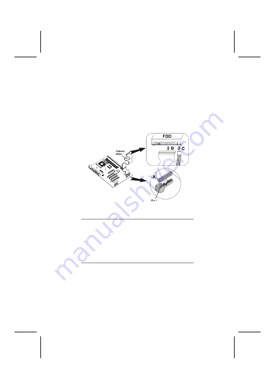
The mainboard has a floppy diskette drive (FDD) interface 
and ships with a diskette drive ribbon cable that supports one 
or two floppy diskette drives. You can install a 5.25-inch drive 
and a 3.5-inch drive with various capacities. The floppy disk-
ette drive cable has one type of connector for a 5.25-inch 
drive and another type of connector for a 3.5-inch drive. 

1.  Install the FDD into the drive cage in your system case. 
2.  Plug the FDD cable into FDD1 (A). 


Note:

  Ribbon cable connectors are usually keyed so that 

they can only be installed correctly on the device 
connector. If the connector is not keyed, make sure 
that you match the pin-1 side of the cable connector 
with the pin-1 side of the device connector. Each 
connector has the pin-1 side clearly marked. The 
pin-1 side of each ribbon cable is always marked 
with a colored stripe on the cable.  

3.  Plug the correct connector on the FDD cable for the 

5.25-inch or 3.5-inch drive into the FDD connector (B). 

4.  Plug a power cable from the case power supply into 

the power connector on the FDD (C). 

When you first start up your system, go immediately to the 
Setup Utility to configure the floppy diskette drives that you 
have installed.  

Содержание P4VXASD

Страница 1: ...specifically disclaims any implied warranties of merchantability or fitness for any particular purpose The manufacturer reserves the right to revise this publication and to make changes from time to...

Страница 2: ...harmful interference to radio or television reception which can be determined by turning the equipment off and on the user is encouraged to try to correct the interference by one or more of the follo...

Страница 3: ...d This device must accept any interference received includ ing interference that may cause undesired operation Canadian Department of Communications This class B digital apparatus meets all requiremen...

Страница 4: ...age 1 Chapter 2 Installing the Mainboard Describes installation of main board components Go to page 7 Chapter 3 Using BIOS Provides information on using the BIOS Setup Utility Go to page 34 Chapter 4...

Страница 5: ...king Jumper Settings 10 Jumper Settings 11 Installing the Mainboard in a Case 14 Connecting Case Components 15 The Panel1 and Panel2 Connectors 16 Installing Hardware 17 Installing the Processor 17 In...

Страница 6: ...e Settings 45 Features Setup Page 45 CPU PnP Setup Page 47 Hardware Monitor Page 48 Change Password 49 Exit 49 CHAPTER 4 50 Using the Mainboard Software 50 About the Software CD ROM 50 Auto installing...

Страница 7: ...four 32 bit PCI slots one 4xAGP slot one CNR Communications and Networking Riser slot and an onboard 10BaseT 100BaseTX Network interface optional In addition this mainboard has a full set of I O ports...

Страница 8: ...cklist Standard Items One mainboard The User s Manual One diskette drive ribbon cable One IDE drive ribbon cable Software support CD One Retention Module Optional Accessories You can purchase the foll...

Страница 9: ...and video performance An ATA 100 interface on the chipset which helps boost system performance by providing a high speed connection to ATA 100 Hard Disk Drives delivering maximum sustained data trans...

Страница 10: ...two backpanel ports onboard USB headers providing four extra ports Audio jacks for microphone line in and line out BIOS Firmware This mainboard uses AMI BIOS that enables us ers to configure many syst...

Страница 11: ...5 M Ma ai in nb bo oa ar rd d C Co om mp po on ne en nt ts s...

Страница 12: ...ll the features required The mainboard can support one floppy diskette drive and four enhanced IDE drives Ensure that your case has sufficient power and space for all the drives that you intend to ins...

Страница 13: ...ling the mainboard Wear a grounding strap attached to a grounded device to avoid damage from static electricity Discharge static electricity by touching the metal case of a safely grounded object befo...

Страница 14: ...Setting Jumpers Go to page 9 Installing the Mainboard in a Case Go to page 14 Installing Case Components Go to page 15 Installing the CPU Go to page 17 Installing Memory Go to page 21 Installing a HDD...

Страница 15: ...iguration op tions Jumpers with more than one pin are numbered When setting the jumpers ensure that the jumper caps are placed on the correct pins Short Open This illustration shows a 2 pin jumper Whe...

Страница 16: ...10 Checking Jumper Settings The following illustration shows the location of the mainboard jumpers Pin 1 is labeled...

Страница 17: ...2 3 133M JP1A1 1 JP1B1 CPU Clock Short 2 3 100M Open 1 2 133M JP1B1 1 JP1 DRAM Volt age Short 1 2 3 3V Open 1 2 2 5V JP1 J2A J2B J2C J2D DDR SDR DRAM Type Selector Short all J2A B C D DDR1 DDR2 Open a...

Страница 18: ...om the mainboard and then move the jumper cap into the CLEAR setting for a few seconds JP1 DRAM Voltage VCC This jumper enables to select voltage of DRAM JP1A1 CPU Clock This jumper enables to select...

Страница 19: ...13 JP3 Flash ROM Voltage VCC This jumper enables to select voltage for Flash ROM JP4 Flash ROM Size This jumper enables to select size for Flash ROM...

Страница 20: ...over tighten the screws as this can stress the mainboard Most system cases have mounting brackets in stalled in the case which correspond to the holes in the mainboard Place the mainboard over the mou...

Страница 21: ...mainboard into a case you can begin connecting the mainboard components Refer to the fol lowing 1 Connect the case power supply connector to CN5 2 Connect the CPU cooling fan cable to CPU_FAN 3 Conne...

Страница 22: ...ns 5 6 10 9 Line Out L Pin 9 10 PANEL2 This panel connector provides a set of switch and LED connectors found on ATX case Refer to the table below for information Device Pins Empty 10 N C 9 Power ON O...

Страница 23: ...talling the Processor This mainboard automatically determines the CPU clock fre quency and system bus frequency for the processor You may be able to change these settings by making changes to jump ers...

Страница 24: ...nd socket is empty Follow these instructions to install the CPU 1 Pull the CPU socket locking lever away from the socket to unhook it and raise the locking lever to the upright position 2 Match the pi...

Страница 25: ...nder the latch on the edge of the socket 4 Apply thermal grease to the top of the CPU 5 Lower the CPU fan heatsink unit onto the CPU and CPU socket and then use the retention module clamps to snap the...

Страница 26: ...20 6 Plug the CPU fan power cable into the CPU cooling fan power supply CPU_FAN on the mainboard...

Страница 27: ...u must install at least one memory module in order to use the mainboard and you can only use one of the both SDRAM and DDR SDRAM at the same time DDR SDRAM provides 800 MBps or 1 GBps data transfer de...

Страница 28: ...slot down 2 Align the memory module with the slot The DIMM slots are keyed with notches and the DIMMs are keyed with cutouts so that they can only be installed correctly 3 Check that the cutouts on t...

Страница 29: ...vices to the secon dary IDE channel IDE devices have jumpers or switches that are used to set the IDE device as MASTER or SLAVE Refer to the IDE device user s manual When installing two IDE devices on...

Страница 30: ...e of each ribbon cable is always marked with a colored stripe on the cable 3 Plug an IDE cable connector into the hard disk drive IDE connector B It doesn t matter which connector on the cable you use...

Страница 31: ...side of each ribbon cable is always marked with a colored stripe on the cable 3 Plug an IDE cable connector into the CD ROM DVD drive IDE connector B It doesn t matter which con nector on the cable y...

Страница 32: ...le connectors are usually keyed so that they can only be installed correctly on the device connector If the connector is not keyed make sure that you match the pin 1 side of the cable connector with t...

Страница 33: ...ts the 4xAGP specifica tions and has a 4xAGP edge connector PCI Slots PCI slots are used to install expansion cards that have the 32 bit PCI interface CNR Slot The Communications Networking Riser CNR...

Страница 34: ...add on card into the expansion slot Ensure that the edge connector is cor rectly seated in the slot 3 Secure the metal bracket of the card to the system case with a screw Note For some add on cards fo...

Страница 35: ...29 Connecting Optional Devices Refer to the following for information on connecting the main board s optional devices...

Страница 36: ...ont mounted ports to the mainboard Pin Signal Name Pin Signal Name 1 3 5 7 9 VCC DATA0 DATA0 GND Key pin 2 4 6 8 10 VCC DATA1 DATA1 GND OC over current detect WOL1 WOM1 Wake On LAN Wake On Modem If yo...

Страница 37: ...onnector is attached to LAN device that needs a LED indicator Pin Signal Name 1 2 3 4 Link LED ACT LED SIR1 Serial infrared port The mainboard supports a Serial Infrared SIR1 data port In frared ports...

Страница 38: ...onal Use the LAN port to connect to the network USB Ports Use the USB ports to connect USB devices LPT1 Use LPT1 to connect printers or other parallel communications devices COM1 2 Use the COM ports t...

Страница 39: ...e out Lime Digital monitor flat panel White IEEE 1394 Grey Microphone Pink MIDI Game Gold Parallel Burgundy PS 2 compatible keyboard Purple PS 2 compatible mouse Green Serial Teal or Turquoise Speaker...

Страница 40: ...c functions of overall coordination between system components If the Setup Utility configuration is incorrect it may cause sys tem s malfunction It can even keep your computer from booting properly If...

Страница 41: ...ke any changes in the future This Setup Utility should be used when changing the system configuration when a configuration error is detected and you are prompted to make changes to the Setup Utility w...

Страница 42: ...date hard disk type etc You can use the cursor arrow keys to highlight any of the op tions on the main menu page Press Enter to select the highlighted option To leave the setup utility press the Esca...

Страница 43: ...d to submenus that enable you to change the values for the option Use the cursor arrow keys to scroll through the items in the submenu In this manual default values are enclosed in parenthesis Submenu...

Страница 44: ...nnected to the Pri mary and Secondary IDE channels To configure an IDE hard disk drive choose Auto If the Auto setting fails to find a hard disk drive set it to User and then fill in the hard disk cha...

Страница 45: ...cheable Enabled SDRAM Timing by SPD Disables SDRAM Frequency 200MHz SDRAM CAS Latency 2 5 SDRAM Bank Interleave Disabled AGP Mode 4X ESC Quit Select Item F1 Help PU PD Modify F5 Old Values Shift F2 Co...

Страница 46: ...y Setup or required both at start up and to enter the Setup Utility Always Boot to OS 2 64MB Enable this item if you are booting the OS 2 operating system and you have more than 64MB of system memory...

Страница 47: ...auto or manual Some AGP cards need stronger than normal driving current in order to operate We recommend that you set this item to the default Manual AGP Comp Driving When AGP Driving is set to Manual...

Страница 48: ...ues Shift F2 Color F6 Load BIOS Defaults F7 Load Setup Defaults ACPI Aware O S This item supports ACPI Advanced Configuration and Power management Interface Use this item to enable or disable the ACPI...

Страница 49: ...power supply in order to use this feature Resume on PME The system can be turned off with a software command If you enable this item the system can automatically resume if there is an incoming call on...

Страница 50: ...IOS Defaults F7 Load Setup Defaults Plug and Play Aware O S Enable this item if you are using an O S that supports Plug and Play such as Windows 95 or 98 PCI Latency Timer This item sets the latency t...

Страница 51: ...ce components Features Setup Page This page sets some of the parameters for peripheral devices connected to the system AMIBIOS SETUP FEATURES SETUP C 2000 American Megatrends Inc All Rights Reserved O...

Страница 52: ...l Port or ECP EPP Parallel Port IRQ Use this item to assign IRQ to the parallel port Parallel Port DMA Use this item to assign a DMA channel to the parallel port OnBoard Game Port This item enables or...

Страница 53: ...installed CPU and make the appropriate adjustments to the items on this page AMIBIOS SETUP CPU PnP SETUP 2000 American Megatrends Inc All Rights Reserved CPU BRAND INTEL CPU Type Pentium 4 CPU Speed...

Страница 54: ...8V 12V 0 907V SB5V 5 053V VBAT 3 488V SYSTEM Fan Speed 0 RPM CPU Fan Speed 5400 RPM Power Temperature 33 C 91 F SYSTEM Temperature 40 C 104 F CPU Temperature 35 C 95 F ESC Quit Select Item F1 Help PU...

Страница 55: ...have retyped it correctly Then the password is required for the access to the Setup Utility or for it at start up depending on the setting of the Password Check item in Ad vanced Setup Exit Highlight...

Страница 56: ...brief description of each software program and the lo cation for your mainboard version More information on some programs is available in a README file and PATH DOC file located in the same directory...

Страница 57: ...the file manager for your OS for example Windows Ex plorer Double click the file setup exe in the root directory Refer to Path doc file for Installation Notes later in this chapter for information on...

Страница 58: ...s only The screens and driver lists will be different according to the mainboard you are installing The mainboard identification is located in the upper left hand corner 2 Click Next The following scr...

Страница 59: ...CD Before installing the software from Windows Explorer look for a file named README TXT PATH DOC or something similar This file may contain important information to help you install the software corr...

Страница 60: ...l li it ty y S So of ft tw wa ar re e R Re ef fe er re en nc ce e All the utility software available from this page is Windows compliant It is provided only for the convenience of custom ers The follo...

Страница 61: ...ion for use with the built in fax modem go the directory UTILITY SUPER_VOICE then run PICSHELL CD Ghost The CD Ghost software enables you to create a virtual cabinet of CD ROM drives on your system to...

Страница 62: ...nius software program run SETUP EXE from the following directory UTILITY LANGUAGE GENIUS ENG LANGUAGEGENIUS PageABC The PageABC application software enables you to create your own home page To install...

Страница 63: ...jumper 1 2 Normal 2 3 Clear CMOS JBAT1 1 JP1A1 CPU Clock Short 1 2 100M Open 2 3 133M JP1A1 1 JP1B1 CPU Clock Short 2 3 100M Open 1 2 133M JP1B1 1 JP1 DRAM Volt age Short 1 2 3 3V Open 1 2 2 5V JP1 J...

Страница 64: ...clear the contents of the CMOS memory You may need to clear the CMOS memory if the settings in the Setup Utility are incorrect and prevent your mainboard from operating To clear the CMOS memory disco...

Страница 65: ...or This jumper enables to select the type of DDR or SDR DRAM JP2 Wake on Keyboard USB activity This jumper enables any USB keyboard activity to power up a system previously in a standby or sleep state...

Страница 66: ...ns 5 6 10 9 Line Out L Pin 9 10 PANEL2 This panel connector provides a set of switch and LED connectors found on ATX case Refer to the table below for information Device Pins Empty 10 N C 9 Power ON O...

Отзывы: